Ink jetting recording device

An inkjet recording and equipment technology, applied in printing, printing devices, etc., can solve the problems of reduced collection efficiency, complex equipment structure, and increased output printing cost.

Inactive Publication Date: 2004-08-11
FUJIFILM CORP
View PDF2 Cites 20 Cited by
  • Summary
  • Abstract
  • Description
  • Claims
  • Application Information

AI Technical Summary

Problems solved by technology

[0005] However, the solvent collecting means used in the conventional inkjet recording apparatus absorbs the air in the entire area inside the inkjet recording apparatus, so there is a problem that in addition to the air containing the solvent component, the solvent collecting means also absorbs the air containing only Air with a small amount of solvent content, such as the atmosphere (the air in the environment of the device) or the external air flowing into the equipment, then the vapor concentration of the solvent content absorbed into the air becomes low, so the collection efficiency will decrease
[0009] However, with the technique disclosed in JP 11-320856 A, when such a printer encounters a situation where, on the printing medium conveyance path, immediately after recording, a device that heats the ink on the printing medium in a non-contact manner is used, Or the device that absorbs the air around the surface of the printing medium immediately after recording, and when the ink solvent sprayed on the printing medium is evaporated for a long time, there will be a problem that the ink solvent that is vaporized by heating or absorption cannot be collected
In addition, for a printer that includes a cover box that covers the entire printing medium conveying path (i.e., the ink ejection part and the entire conveying path), there are problems of complicated device structure and increased size of the device
In addition, for printers that use heating means or absorbing means provided immediately after the inkjet head to accelerate the evaporation of ink solvent, or for printers that use a cover box that covers the entire printing medium conveyance path and ink ejection parts, there is a problem of inkjet head deformation. Problems with adverse effects caused by changes in viscosity of dry or jetted inks
In addition, for a printer including a device that forms an ink vaporization inhibitor layer on a printing medium immediately after recording, there is a problem of an increase in output printing cost

Method used


Image

  • Ink jetting recording device
  • Ink jetting recording device
  • Ink jetting recording device

Examples


no. 1 example

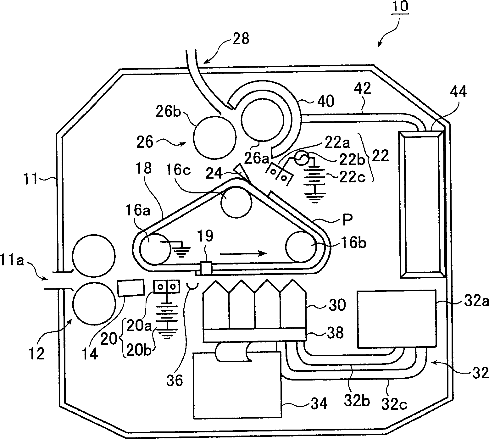
[0036] figure 1 is a schematic configuration diagram showing the general configuration of the first embodiment of the inkjet recording apparatus according to the present invention.

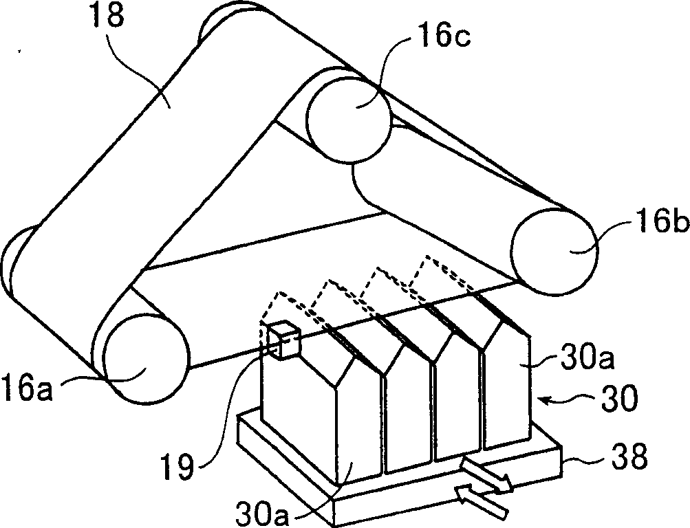
[0037] By using the image forming device, an image composed of ink particles (pigment particles) is formed on the recording medium P conveyed by the conveying device by ejecting ink droplets of four colors according to the input image data, and aligned on the recording medium P. The image composed of the formed ink particles is fixed (fixed or fixed), figure 1 The illustrated electrostatic inkjet recording apparatus 10 (hereinafter referred to as "inkjet printer") enables recording of full-color images. In addition, the inkjet printer 10 also collects air containing a large amount of ink solvent vapor from an area near the fixing / conveying device 26 using collecting means, and removes the solvent in the collected air using removing means.

[0038] figure 1 The illustrated inkjet printer 10 is a...

no. 2 example

[0154] Hereinafter, a second embodiment of the inkjet recording apparatus of the present invention will be described.

[0155] Figure 6 The inkjet printer 100 has the same figure 1 The inkjet printer 10 shown in is substantially the same in structure and function. The difference between the inkjet printer 100 and the inkjet printer 10 is: when the image is formed, the recording medium P is not directly powered; an insulating conveyor belt 112 is used; The counter electrode of the electrostatic adsorption device 116 and the static elimination device 117, which each use a conductive roller; a certain preheating device 118 is arranged between the static removal device 117 and the fixing / transfer device 26; and the removal cover 40 and In addition to the delivery pipe 42 as a collection device for solvent-containing air, a blower device 119 is also provided. In the following description, elements of the same structure as those of the inkjet printer 10 are assigned the same ref...

no. 3 example

[0175] A third embodiment of the ink jet recording apparatus of the present invention will be described below.

[0176] Figure 7 The illustrated inkjet printer 120 includes a recording medium storage cassette 122 that can be inserted into and removed from a housing 121 . As a device for conveying the recording medium P, the inkjet printer 120 includes: a pick-up roller 124; a pair of feed rollers 126; a dust removal device 128; rollers 130a, 130b, and 130c; a conveyor belt 132; ; a separation or peeling device 140 ; ​​a fixing device 142 ; and a discharge roller pair 144 . With this structure, the recording medium P stored in the paper storage cassette 122 is conveyed to each processing step, and then output on the paper output pallet 146 .

[0177] In addition, as an image forming device, the inkjet printer 120 includes: a platen 148; an inkjet head 150; an ink circulation system 152; an inkjet head driver 154; a recording medium position detecting device 156; Position co...


PUM


Abstract

The ink jet recording apparatus (10) includes an image forming device for forming an image on a recording medium (P) by ejecting ink containing a solvent and color particles dispersed in the solvent, a fixing device (26) for fixing the image formed on the recording medium by the image forming device, a collecting device (40,42) for selectively collecting air containing the solvent from an atmosphere in proximity to the fixing device, and a removing device (44) for removing the solvent from the solvent-containing air collected by the collecting device.

Description

technical field [0001] The present invention relates to an inkjet recording apparatus which records an image on a recording medium by an inkjet system using an ink in which pigment particles (colorant components) are dispersed in a solvent (dispersion medium). More particularly, the present invention relates to an inkjet recording apparatus capable of efficiently collecting solvent vapor generated from ink. Background technique [0002] An electrostatic inkjet recording system is a system in which: the ink used contains pigment particles (such as pigments) which are charged and dispersed in a certain solvent; An electrostatic force generated by a predetermined voltage ejects ink (droplets) to form an image corresponding to image data on a recording medium. Then, using a certain fixing device (fixing device), the image formed on the recording medium by the ejected ink is fixed or fixed, for example, heated, thereby removing the solvent component in the ink and only fixing or...

Claims


Application Information

Patent Timeline
Patent Type & Authority Applications(China)
IPC IPC(8): B41J2/01B41J2/06B41J11/00B41J13/03B41J13/10
CPCB41J11/007B41J29/377B41J13/03B41J11/002B41J13/106B41J11/0095B41J2/06B41J13/103B41J11/0024B41J11/00216B41J11/0022
Inventor 中沢雄祐
Owner FUJIFILM CORP
Why Eureka
Try Eureka