Vehicle brake system, and method of controlling such brake system

A braking system and braking control technology, applied in the direction of the brake, can solve the problem of the reduction of the braking force

Inactive Publication Date: 2004-08-11
TOYOTA JIDOSHA KK +1
View PDF3 Cites 33 Cited by
  • Summary
  • Abstract
  • Description
  • Claims
  • Application Information

AI Technical Summary

Problems solved by technology

[0008] However, in the related art braking system, the braking force may sometimes decrease depending on the road surface conditions during the ABS control process.

Method used


Image

  • Vehicle brake system, and method of controlling such brake system
  • Vehicle brake system, and method of controlling such brake system
  • Vehicle brake system, and method of controlling such brake system

Examples


Embodiment Construction

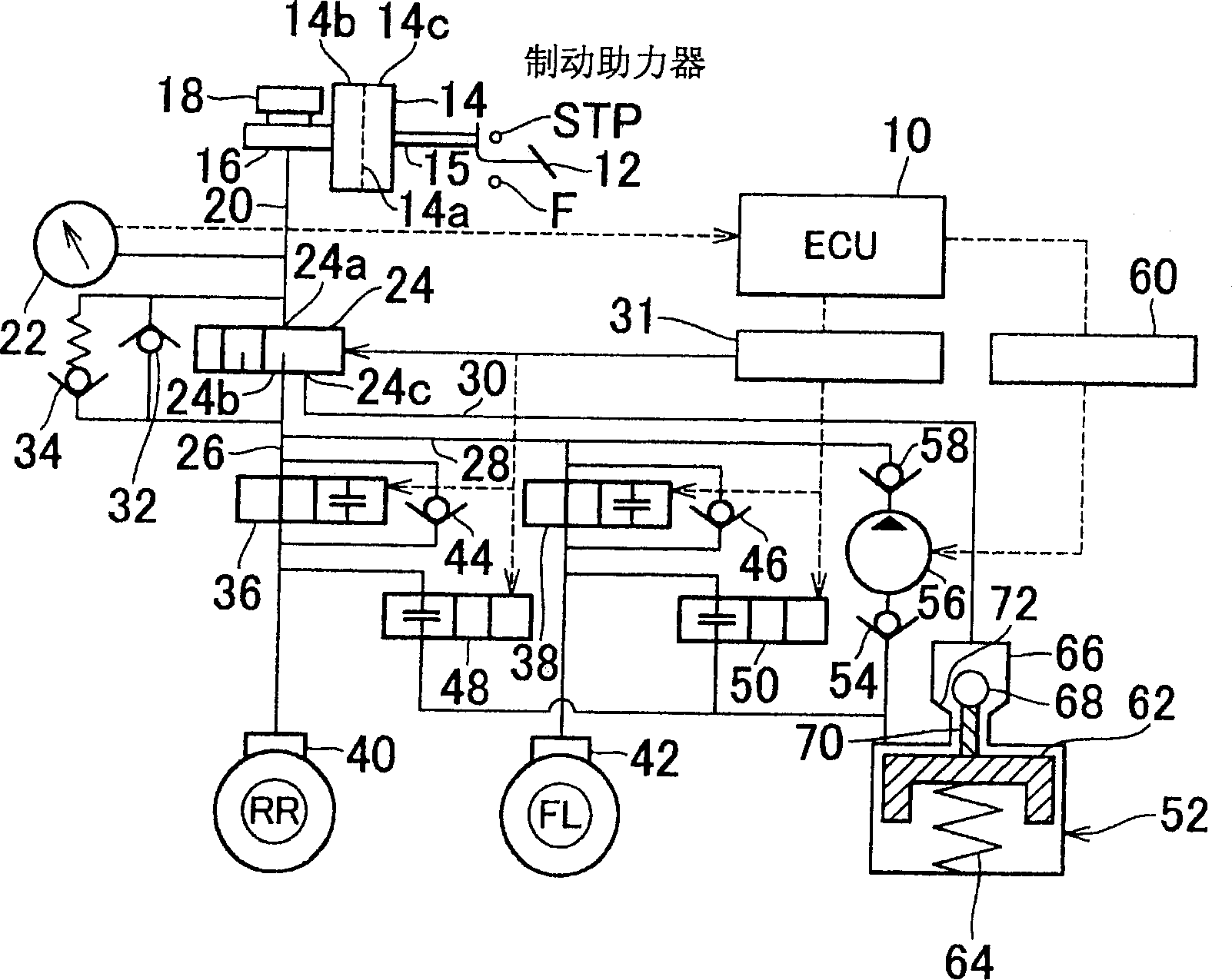
[0039] Preferred embodiments of the present invention will be described below with reference to the accompanying drawings. The same components and parts are denoted by the same reference numerals, and descriptions will not be repeated below. figure 1 Shown is a simplified diagram of the structure of a braking system according to an embodiment of the present invention.

[0040] The brake system of this embodiment is a hydraulic brake device, and is controlled by an electronic control unit (hereinafter referred to as “ECU”) 10 . figure 1 Shown are the components constituting the braking mechanism of the left front wheel FL and the right rear wheel RR. First, the brake hydraulic system will be described.

[0041] The braking force control device includes a brake pedal 12 . The brake pedal 12 is connected to a power shaft 15 of a brake booster 14 . The master hydraulic cylinder 16 is fixed to the brake booster 14 . Inside the brake booster 14 are a constant pressure chamber 1...


PUM


Abstract

The brake system of the invention, during the ABS control mode, corrects the target slip rate in accordance with the turning of the vehicle, and determines whether the vehicle is running on a poor surface road. If the vehicle is running on a poor surface road, the system sets a target slip rate that provides a greater longitudinal force than the aforementioned target slip rate.

Description

technical field [0001] The invention relates to a braking system and a method of controlling the braking system. Background technique [0002] An anti-skid (anti-lock) braking system (ABS) that prevents the wheels from locking up during emergency braking and allows steering maneuvers during emergency braking, a system commonly known as an active safety device . [0003] The braking systems described below are known. [0004] (1) A system whose anti-lock brake control changes according to an index indicative of the momentum of a traveling vehicle (see Japanese Patent Application Laid-Open No. 10-6968). [0005] (2) A system that considers a physical quantity indicative of a vehicle running state in determining an ABS control strategy (see Japanese Patent Application Laid-Open No. 19512766). [0006] (3) A system that sets a control amount required for antilock control based on a deviation between an actual yaw rate and a target yaw rate (see Japanese Patent Application Lai...

Claims


Application Information

Patent Timeline
Patent Type & Authority Applications(China)
IPC IPC(8): B60T8/1755B60T8/1764B60T8/58B60T8/88
CPCB60T2210/16B60T8/885B60T8/1755B60T2210/14B60T8/1764
Inventor 二瓶寿久原雅宏松浦正裕堂浦阳文
Owner TOYOTA JIDOSHA KK
Why Eureka
Try Eureka