Transmission line having photonic band gap coplanar waveguide structure and method for fabricating power divider using the same

A power divider and coplanar waveguide technology, which is applied in the field of transmission lines, can solve the problems of easy breakage of signal lines, difficulty in manufacturing, and difficulty in high-impedance transmission lines.

Inactive Publication Date: 2004-08-18
LG ELECTRONICS INC
View PDF1 Cites 5 Cited by
  • Summary
  • Abstract
  • Description
  • Claims
  • Application Information

AI Technical Summary

Problems solved by technology

For this reason it is difficult to implement transmission lines with high impedance
[0011] Furthermore, since the power divider according to the prior art distributes high power in a high frequency band and requires high characteristic impedance, it is difficult to apply a transmission line having a PBG CPW structure to the power divider according to the prior art
That is, signal lines with a narrow width are easily cracked and difficult to manufacture

Method used


Image

  • Transmission line having photonic band gap coplanar waveguide structure and method for fabricating power divider using the same
  • Transmission line having photonic band gap coplanar waveguide structure and method for fabricating power divider using the same
  • Transmission line having photonic band gap coplanar waveguide structure and method for fabricating power divider using the same

Examples


Embodiment Construction

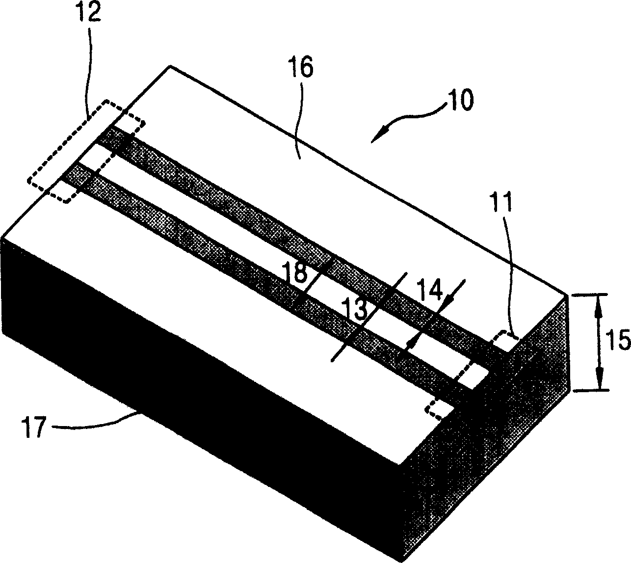
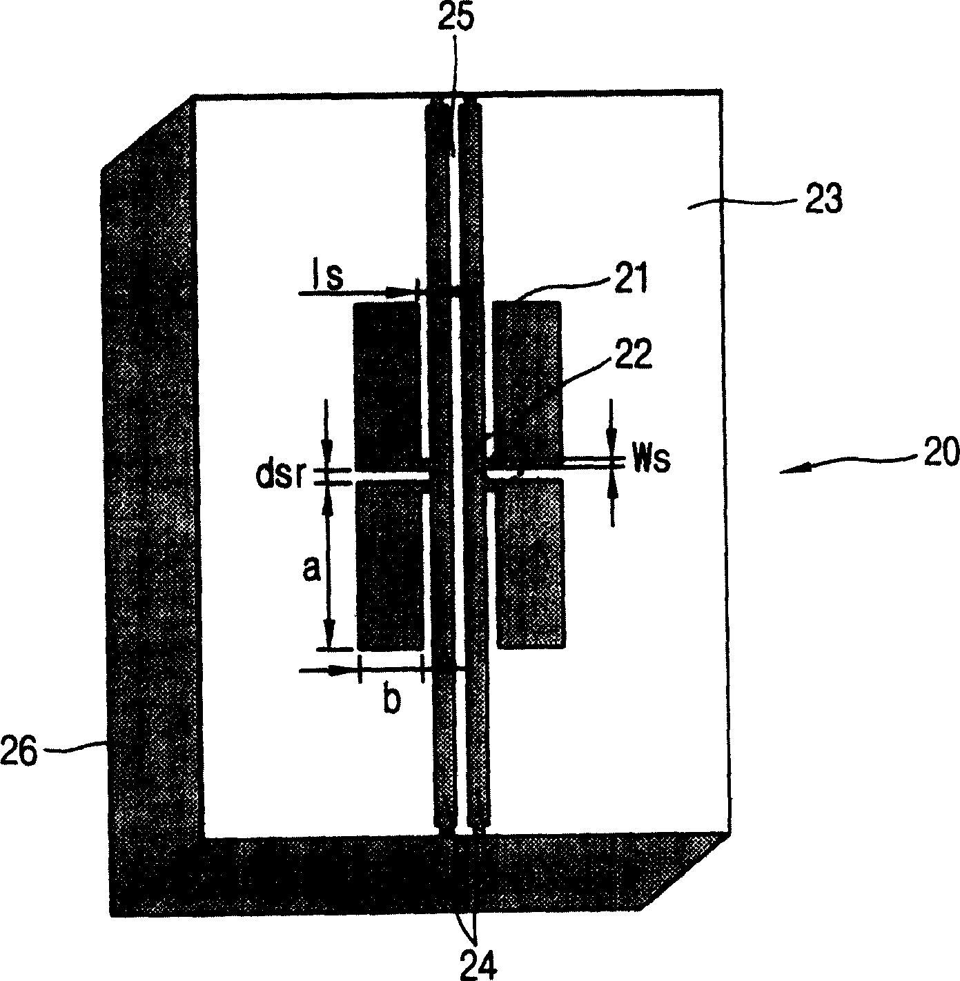
[0033] In the following, reference will be made to Figure 2-11 A preferred embodiment of a transmission line having a photonic bandgap (PBG) coplanar waveguide (CPW) structure and a method of using the transmission line to fabricate a power divider that increases the characteristic impedance, increases the signal line width of the transmission line, and provides high power is described.

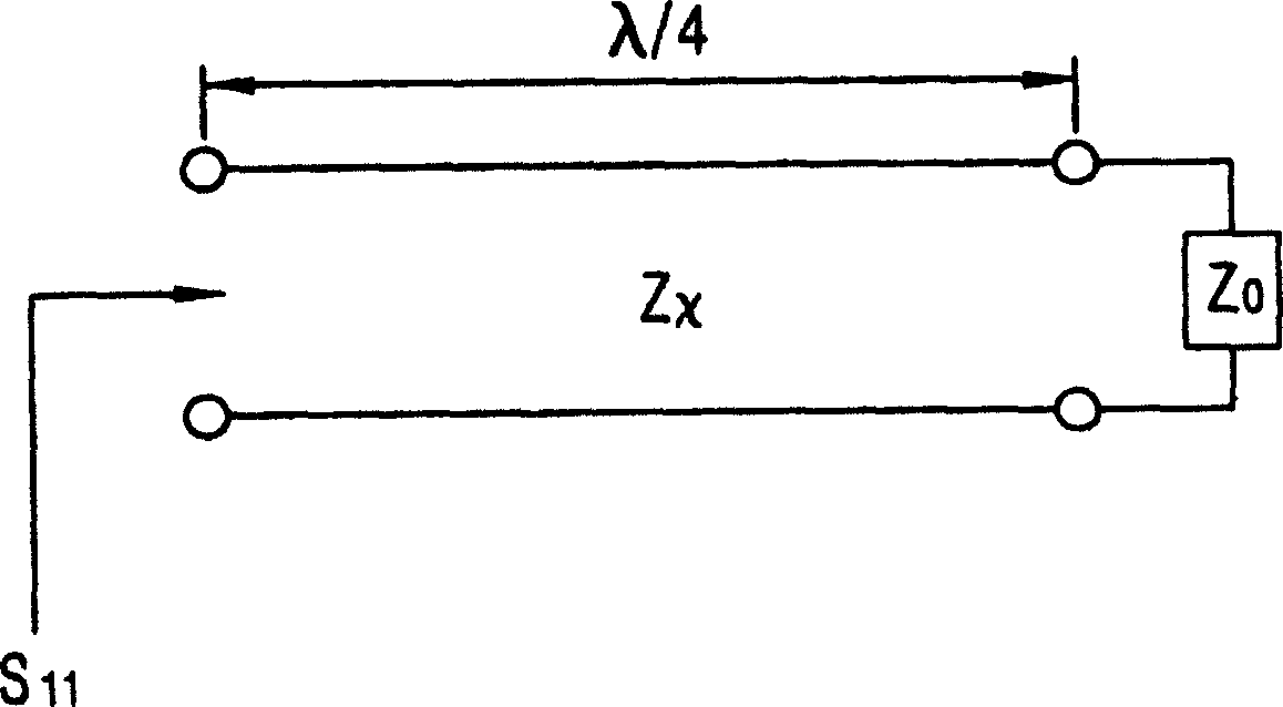
[0034] figure 2 is a diagram for describing the present invention showing a normal transmission line with its load side short-circuited.

[0035] As shown in the figure, when the load terminal (load impedance Z o ) is short-circuited, the characteristic impedance of the transmission line becomes Z X . Here, the input end of the transmission line S 11 is the reflection coefficient.

[0036] When the length of the transmission line is λ / 4, the characteristic impedance of the transmission line (Z X ) coincides with the maximum reflection coefficient value and can be obtained from the sig...


PUM

PropertyMeasurementUnit
widthaaaaaaaaaa
thicknessaaaaaaaaaa
widthaaaaaaaaaa

Abstract

A photonic band gap coplanar waveguide transmission line and a method for fabricating a power divider using the same capable of increasing a characteristic impedance, increasing a signal line width of the transmission line and providing high power, includes: a ground conductive layer formed on a substrate; linear grooves formed on the ground conductive layer; a signal line formed between linear grooves; rectangular grooves formed close to the signal line, and formed on the ground conductive layer; and slots formed at the rectangular grooves respectively, and connecting the rectangular groove and the linear groove.

Description

technical field [0001] The invention relates to a transmission line, in particular to a transmission line with a photonic bandgap (PBG) coplanar waveguide (CPW) structure and a method for manufacturing a power divider using the transmission line. Background technique [0002] Generally, the most important factors when designing a transmission line are an appropriate eigenvalue and the maximum received power of the transmission line. The maximum received power refers to the power limit value that the transmission line can withstand. That is, even if a transmission line has an exact characteristic value, if a power higher than the maximum received power is applied to such a transmission line, the transmission line itself will break. [0003] figure 1 Denotes a transmission line with a general coplanar waveguide (CPW). [0004] As shown in the figure, a signal applied to the input terminal 11 of the transmission line 10 generates electric and magnetic fields through the spac...

Claims


Application Information

Patent Timeline
Patent Type & Authority Applications(China)
IPC IPC(8): H01L21/00H01P3/00H01P5/16
CPCH01P5/16H01P3/003H01P1/2005H01L21/00
Inventor 高英俊朴宰永
Owner LG ELECTRONICS INC
Why Eureka
Try Eureka