Defrosting device of air heat exchanger

A technology for heat exchangers and fans, which is applied in the field of defrosting devices for air heat exchangers, and can solve problems such as affecting the defrosting effect, reducing the surface temperature of the heat exchanger, and the heat exchanger cannot be forced to cool when the fan is turned off.

Inactive Publication Date: 2004-09-29
储维
View PDF0 Cites 18 Cited by
  • Summary
  • Abstract
  • Description
  • Claims
  • Application Information

AI Technical Summary

Problems solved by technology

[0006] 1. Frosted air heat exchangers usually only frost on the air inlet side and not on the air outlet side. The temperature on the non-frost side is higher, and the air near the non-frost side rises after being heated by the heat exchanger without being frosted. Used for defrosting on the frosted side
[0007] 2. The water formed after the frost melts seeps into the gaps of the heat exchange fins, and is heated and eva

Method used


Image

  • Defrosting device of air heat exchanger
  • Defrosting device of air heat exchanger
  • Defrosting device of air heat exchanger

Examples


Embodiment approach

[0026] Install a circuit to start (or stop) the forward and reverse of the fan in the air-cooled refrigerator, such as Figure 4 , Figure 5 . in Figure 4 It is the electrical schematic diagram of starting (or stopping) forward and reverse fan for ordinary three-phase asynchronous motor through the switching of AC contactor and exchanging two-phase power supply. refer to Figure 4 : When the normally open contact [2k] of the fan motor AC contactor [2] is disconnected and the normally open contact [1k] of the fan motor AC contactor [1] is closed, the fan motor [3] is energized and rotates forward, and When the normally open contact [1k] of the fan motor AC contactor [1] is disconnected and the normally open contact [2k] of the fan motor AC contactor [2] is closed, the fan motor [3] is energized and reversed. Figure 5 It is the electrical schematic diagram of starting (or stopping) the forward and reverse fan for the single-phase motor through the switching of the AC conta...


PUM


Abstract

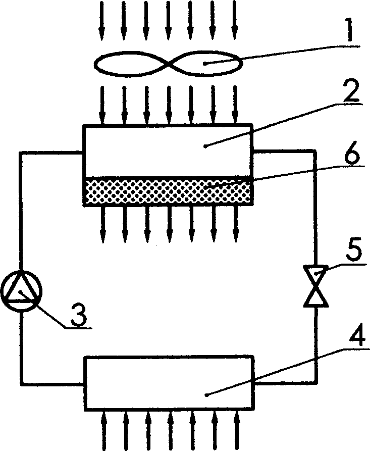
The present invention relates to defrosting device of air heat exchanger. During defrosting, the special defrosting fan is controlled via time, temperature or pressure to blow in the opposite direction to normal direction, so that air is forced to flow from the no-frost side to the frosted side in the air heat exchanger and heated air is blown to the frost layer for thawing in convection, heat conducting and radiation modes.

Description

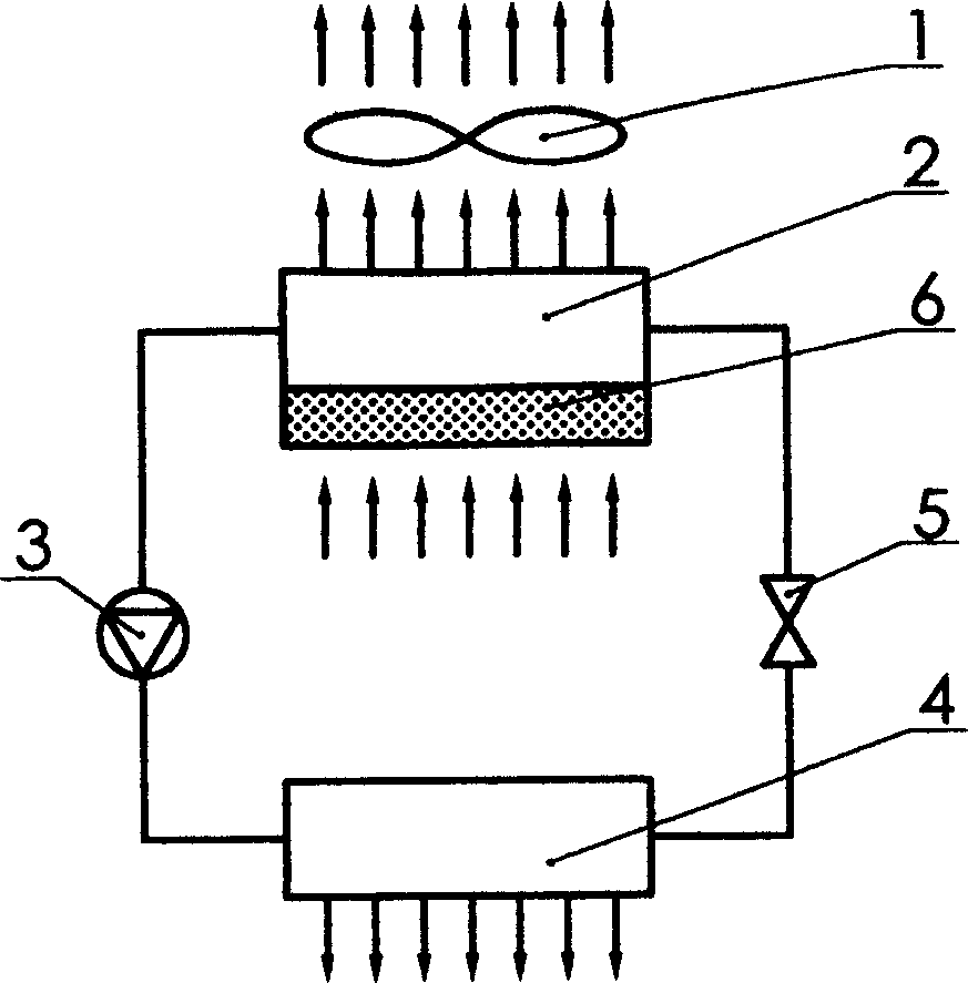
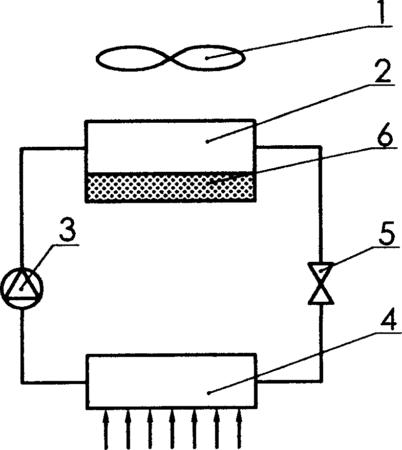
technical field [0001] Air-cooled refrigerator Background technique [0002] Air-cooled refrigerators usually have two heat exchangers, one for heat release and one for cooling, one example of which is an air-cooled air conditioner. Let's take the air-cooled air conditioner as an example to illustrate the working condition of the heat exchanger. refer to figure 1 : The air-cooled air conditioner starts the fan [1] to force the air to pass through the air heat exchanger [2] when the air-cooled air conditioner is heating in winter, and the liquid refrigerant absorbs the heat in the air in the air heat exchanger [2]. The refrigerant is compressed by the compressor [3] and becomes a high-temperature and high-pressure gas, which is sent to the heat exchanger [4] to release heat, and the gaseous refrigerant is condensed into a high-pressure liquid state. The high-pressure liquid refrigerant enters the air heat exchanger [2] after being throttled by the expansion valve [5] to ab...

Claims


Application Information

Patent Timeline
IPC IPC(8): F25B47/02
Inventor 储维
Owner 储维
Why Eureka
Try Eureka