Intensified component, connector with the component, connection mechanism of electric component and substrate

A technology of connectors and components, which is applied in the field of reinforcement components, can solve the problems of reduced effective installation area, poor connection, and twisting stress imposed by connectors, and achieves the effects of increased joint strength, improved bearing capacity, and expanded joint area

Inactive Publication Date: 2004-10-20
JST MFG CO LTD
View PDF1 Cites 2 Cited by
  • Summary
  • Abstract
  • Description
  • Claims
  • Application Information

AI Technical Summary

Problems solved by technology

However, if the bonding area is enlarged, the effective mounting area of ​​the electronic components mounted on the substrate will be reduced
In addition, if a large amount of solder is used, since the wiring pattern of the substrate is very thin, if solder is applied across multiple wiring patterns, poor connection is likely to occur, so it is not preferable.
[0015] In addition, it is conceivable to provide a through-hole on the substrate and to stabilize it by inserting a reinforcing member into the through-hole, but this is not preferable because the effective mounting area of ​​the electronic component on the back side of the substrate will be reduced.
[0016] In addition, sometimes the opposite connector like a game card needs to be pulled out and inserted frequently from the connector. In this case, when the user pulls out the game card from the connector, it is necessary to twist the connector to pull the game card, thus sometimes subjecting the connector to twisting stress
At this time, since the torsional stress is concentrated on the joint between the connector and the board, the joint between the connector and the board may be weakened, causing the above-mentioned problems.
[0017] In addition, the above-mentioned problems are not limited to connectors, but also easily occur on electrical components. Due to manual operation of people, external forces from various directions will be applied to electrical components.
For example, surface-mounted electrical components such as DIP switches that have multiple switches and can produce circuit changes are prone to the above problems

Method used


Image

  • Intensified component, connector with the component, connection mechanism of electric component and substrate
  • Intensified component, connector with the component, connection mechanism of electric component and substrate
  • Intensified component, connector with the component, connection mechanism of electric component and substrate

Examples


Embodiment Construction

[0052] Next, embodiments of the reinforcing member and the connector equipped with the reinforcing member according to the present invention will be described with reference to the drawings. But the present invention is not limited thereto. In addition, in the following description, the same symbol will be attached to the same component, and description will be omitted or simplified. In addition, directional terms such as front, rear, left, right, up, and down used in the following embodiments are used only for convenience of description.

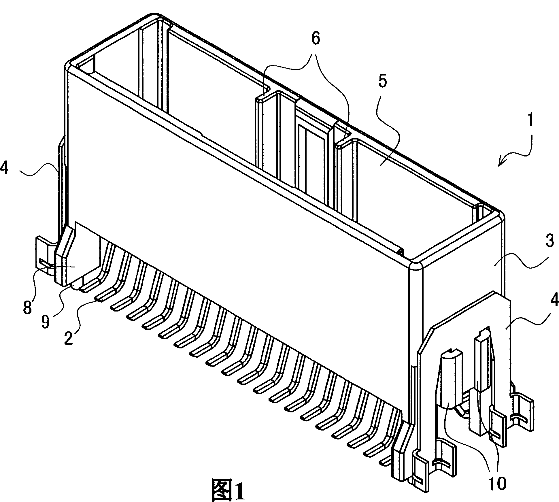
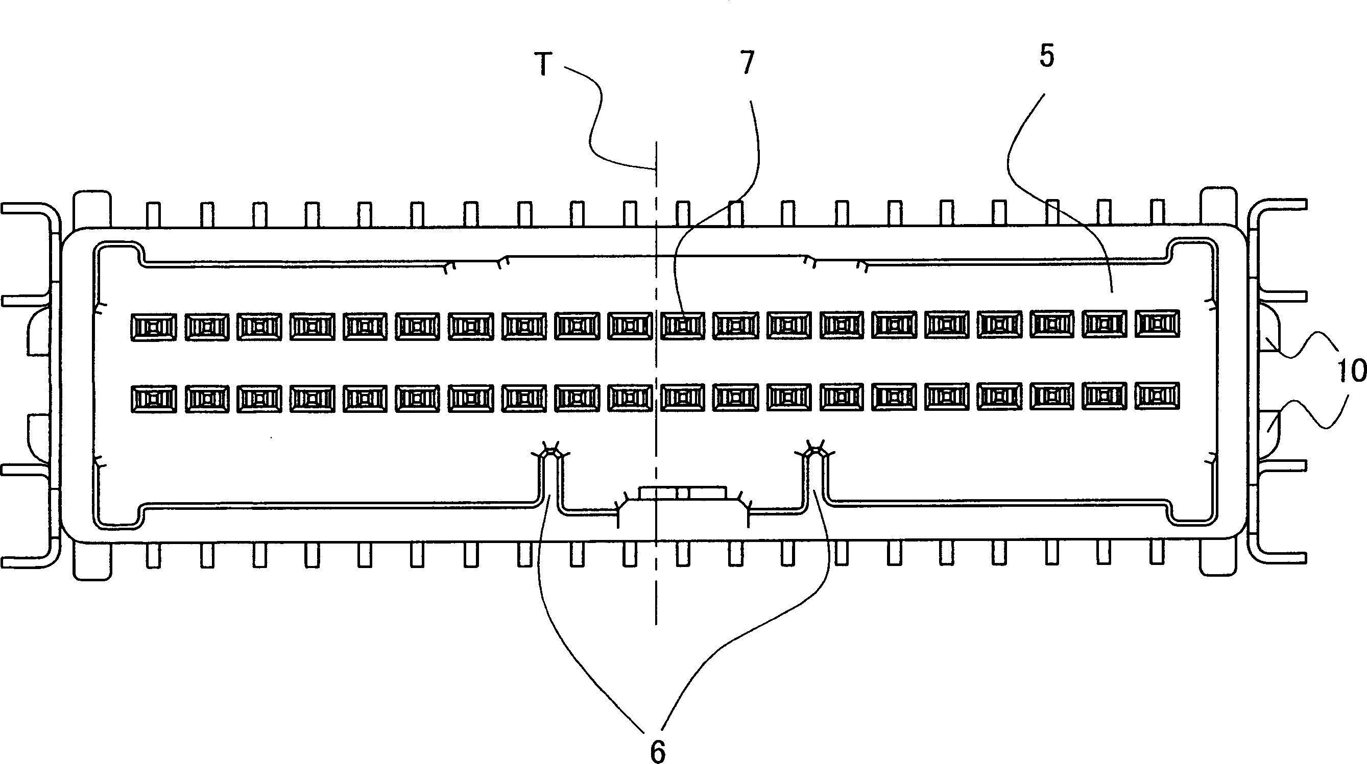
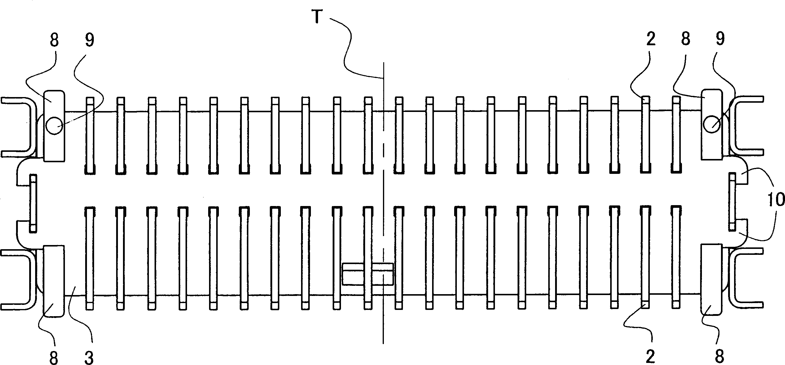
[0053] Fig. 1 is a perspective view of a connector provided with reinforcing members of the present invention. figure 2 is a top view of the connector. image 3 is a bottom view of the connector. Figure 4 is the front view of the connector. Figure 5 is a side view of the connector.

[0054] The connector 1 has an integrally molded housing 3 made of insulating resin, and the housing 3 is provided with a plurality of metal pin contacts...


PUM


Abstract

PURPOSE: A reinforcing tap, a connector including the reinforcing tap, and a connecting structure of an electrical component and a board are provided to maintain the connection of the connector and the board even when a large external stress is applied to the connection structure or the connection structure is placed in a high-temperature environment. CONSTITUTION: A reinforcing tap(4) is attached to a housing(3) of a surface mounting connector(1). The housing has a shorter side and a longer side. The reinforcing tap has a portion attached to the longer side of the housing and a portion bonded to a circuit board. The bonded portion has a bonding plane perpendicular to the shorter and longer sides. The bonding plane has the first face parallel with the shorter side of the housing and the second face parallel with the longer side of the housing. The second face is connected to the first face through a curved face to face the housing.

Description

technical field [0001] The present invention relates to a reinforcing member for reinforcing the bonding between a surface mount type connector in which a pin connector is surface mounted on a circuit substrate and a circuit substrate. In addition, the present invention also relates to a connection structure for connecting a connector equipped with the reinforcing component, and an electrical component equipped with the connector or a DIP switch with a board. Background technique [0002] Conventionally, as a connector that is bonded to a circuit board such as a printed wiring board using surface mount technology, there is known a surface mount connector (hereinafter, It is called "SMT (surface-mount-technology) connector." The SMT connector has a case with an opening for inserting a mating connector, and a plurality of pin connectors are arranged in parallel at predetermined intervals in the case. [0003] For SMT connectors, the part connected to the opposite connector (h...

Claims


Application Information

Patent Timeline
Patent Type & Authority Applications(China)
IPC IPC(8): H01R13/46
CPCB65D25/02B65D2517/0094
Inventor 高木义一宫原和志
Owner JST MFG CO LTD
Why Eureka
Try Eureka