Electromagnetic driver and exposure reglation component using it

A drive, electromagnetic technology, applied in the field of electromagnetic drive, exposure adjustment components, can solve the problem of increasing the volume of the magnet

Inactive Publication Date: 2004-10-20
ALPS ALPINE CO LTD
View PDF2 Cites 3 Cited by
  • Summary
  • Abstract
  • Description
  • Claims
  • Application Information

AI Technical Summary

Problems solved by technology

[0010] However, when outputting high torque with the device shown in Patent Document 1, it is necessary to increase the volume of the magnet as the movable part, resulting in an increase in the size of the device.

Method used


Image

  • Electromagnetic driver and exposure reglation component using it
  • Electromagnetic driver and exposure reglation component using it
  • Electromagnetic driver and exposure reglation component using it

Examples


Embodiment Construction

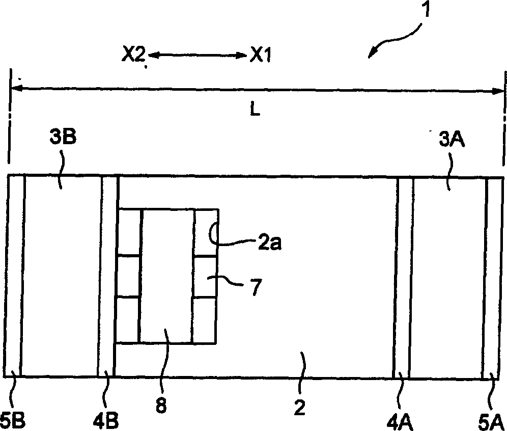
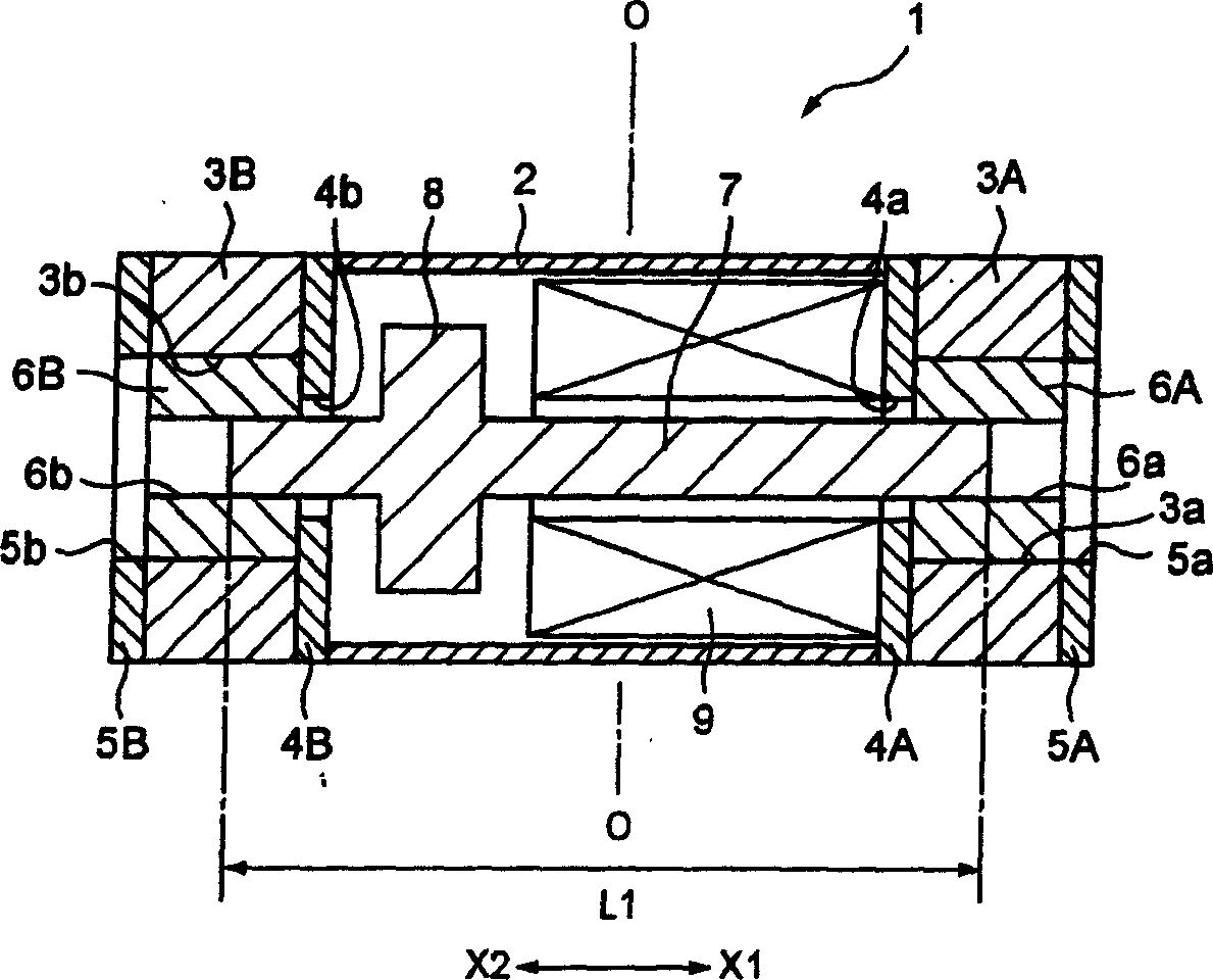
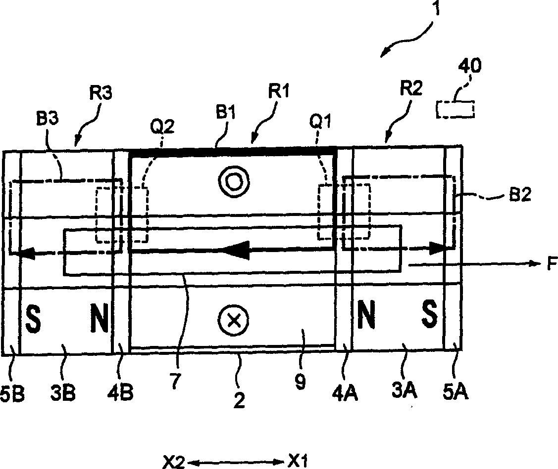
[0031] figure 1 Is a plan view showing an example of the appearance of the electromagnetic actuator of the present invention, figure 2 Is a cross-sectional view of the electromagnetic drive, image 3 It is a schematic diagram showing the flow of the magnetic field inside the electromagnetic actuator. Figure 4 It is a graph showing the relationship between the attractive force to the shaft and the amount of displacement, Figure 5 It is a graph showing the relationship between the driving force generated by the coil and the amount of displacement.

[0032] Such as figure 1 As shown, the electromagnetic actuator 1 of this embodiment has a cylindrical barrel 2. The cylinder 2 is made of magnetic materials such as iron or ferrite. In addition, the cylindrical body 2 is formed with a quadrangular opening 2a penetrating along its curved surface.

[0033] Such as figure 2 As shown, on the X1 side and X2 side of the cylinder 2, magnets 3A and 3B made of permanent magnets are respect...


PUM


Abstract

Provided is a device in which a movable part is low in mass, and moreover, which can output a high torque. In a first magnetic circuit and a second magnetic circuit, both end sides of a shaft 7 are freely slidably supported by bearings 6A, 6B. Further, first yokes 4A, 4B, magnets 3A, 3B, and second yokes 5A, 5B are provided around the bearings 6A, 6B. Also, a driving coil 9 is provided around the shaft 7. The magnetic flux becomes large in one of the overlapped parts of a magnetic circuit generated at the start of the driving coil 9 and the first magnetic circuit or the second magnetic circuit, and the magnetic flux becomes small in the other overlapped part. As a result, the shaft 7 is moved in the direction to the portion where the magnetic flux is large.

Description

Technical field [0001] The present invention relates to an electromagnetic driver assembled on image equipment such as a digital camera and an exposure adjustment member using the electromagnetic driver, and in particular to an electromagnetic driver that is small and can obtain a high torque output and an exposure adjustment using the same member. Background technique [0002] Patent Document 1 described below describes a shutter device that also serves as an aperture for a camera. The device is provided with a plurality of blades that act in synchronization with each other and a solenoid that drives the blades. The solenoid is supported with an iron core so that it can advance and retreat freely. In addition, the iron core is provided with an urging member that urges in the direction of protrusion. By energizing the solenoid to oppose the urging force of the urging member, each blade moves in the opening direction. By canceling the energization of the solenoid, the urging force...

Claims


Application Information

Patent Timeline
Patent Type & Authority Applications(China)
IPC IPC(8): G03B9/02G03B9/08H01F7/16H02K33/16H02K41/00
Inventor 涌田宏
Owner ALPS ALPINE CO LTD
Why Eureka
Try Eureka