Assembling structure of microwave oven

An assembly structure and microwave oven technology, applied in the field of microwave ovens, can solve the problems of difficult assembly, complex manufacturing process, increased production cost, etc., and achieve the effects of maintaining a combined state, reducing production costs, and stabilizing a combined state.

Inactive Publication Date: 2004-10-27
LG ELECTRONICS (TIANJIN) APPLIANCES CO LTD
View PDF0 Cites 1 Cited by
  • Summary
  • Abstract
  • Description
  • Claims
  • Application Information

AI Technical Summary

Problems solved by technology

[0014] As described above, the assembly structure of the existing microwave oven requires many screw connections, so the manufacturing process is very complicated, thereby causing problems such as an increase in the overall production cost.
[0015] Not only that, if the screw is lost due to the screw disengagement during the use of the microwave oven, the stable combination of the microwave oven cannot be guaranteed, and vibration caused by the drive of the motor (not shown) will occur
[0016] It is particularly worth noting that the assembly structure of existing microwave ovens does not consider the relative movement in the up-and-down direction and the relative movement in the front-to-back direction between the various components, resulting in misalignment between the screw connection holes, which brings difficulties to assembly
The above-mentioned assembly is realized through several screw connections, and the overall assembly efficiency is not ideal

Method used


Image

  • Assembling structure of microwave oven
  • Assembling structure of microwave oven
  • Assembling structure of microwave oven

Examples


Embodiment Construction

[0030] Embodiments of the present invention are described below with reference to the accompanying drawings:

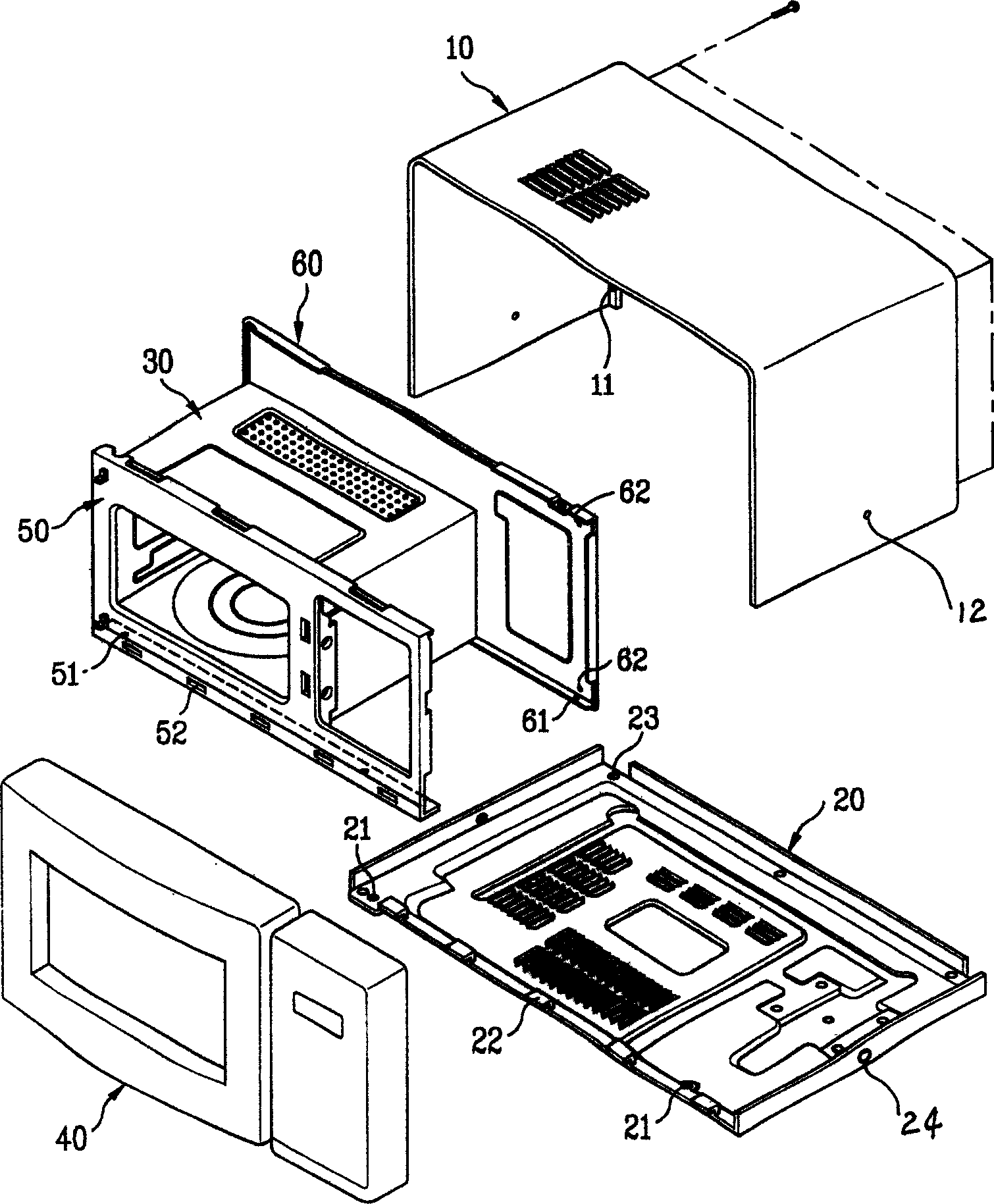
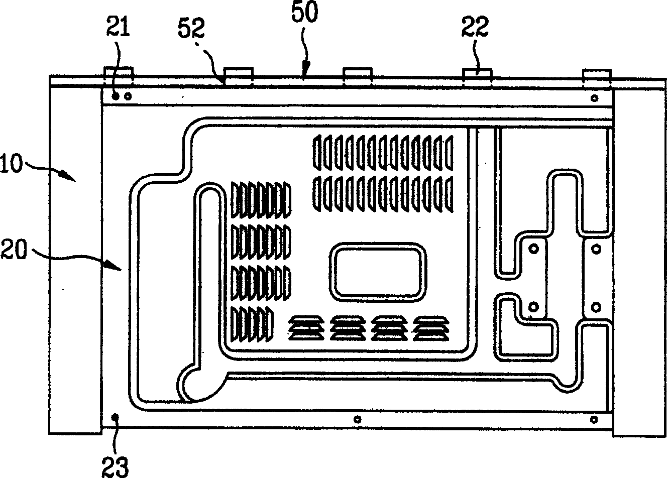
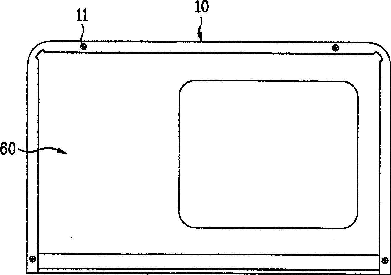
[0031] The present invention is an assembly structure of a microwave oven, which mainly includes a cavity 300 with a cooking chamber, a base plate 200 located at the bottom of the microwave oven and a shell 100 surrounding the cavity; a front frame 500 is arranged on the front side of the cavity , the rear side of the cavity has a rear frame 600, the bottom of the front frame 500 has a first opening 510, the bottom of the rear frame 600 has a second combination protrusion 610, and the front end of the base plate 200 has a The first coupling protrusion 210 corresponds to the first opening 510 of the front frame 500 , and the second opening 220 corresponds to the second protrusion 610 of the rear frame 600 at the rear end of the base plate 200 .

[0032] The first combining protrusion 210 of the base plate 200 is formed by cutting its bottom to the left or right and pro...


PUM


Abstract

An assembling structure for microwave oven is composed of an empty cavity with cooking chamber, base plate as the bottom of microwave oven, casing surrounding said empty cavity, front frame and back frame. It features that the holes on the bottom of front frame and the lugs on the bottom of back frame are respectively matched with the lugs at front end of base plate and the holes at back end of base plate. Its advantages are easy assembling, less screws, and high stability.

Description

technical field [0001] The invention relates to a microwave oven, in particular to a simple assembly structure between parts of the microwave oven. Background technique [0002] Generally speaking, a microwave oven is an electrical device that uses high-frequency waves (about 2,450 MHz per second) as a heating source to cook food by breaking the order of food molecules and causing frictional heat generated by high-speed oscillation of molecules. [0003] Such as figure 1 As shown, such a microwave oven is generally composed of a casing 10 forming the outer surface, a base plate 20 forming the bottom surface, a cavity 30 with a cooking chamber, and a microwave oven door 40 for opening and closing the cavity. [0004] The aforementioned housing 10 surrounds a cavity 30, which protects the cavity from the external environment. [0005] A front frame 50 and a rear frame 60 are respectively arranged at the front and rear of the cavity 30 , which are combined with the casing 10 ...

Claims


Application Information

Patent Timeline
Patent Type & Authority Applications(China)
IPC IPC(8): F24C7/02
Inventor 金培镇
Owner LG ELECTRONICS (TIANJIN) APPLIANCES CO LTD
Why Eureka
Try Eureka