Circuit providing output in three electrical levels for correcting two-phase power factor

A technology of three-phase power and correction circuit, which is applied in the direction of output power conversion device, high-efficiency power electronic conversion, electrical components, etc., and can solve the problems of large device stress and complex control strategy

Inactive Publication Date: 2004-10-27
ZTE CORP
View PDF1 Cites 18 Cited by
  • Summary
  • Abstract
  • Description
  • Claims
  • Application Information

AI Technical Summary

Problems solved by technology

Since the circuit has only one switch tube, the control strategy is complicated, and the s

Method used


Image

  • Circuit providing output in three electrical levels for correcting two-phase power factor
  • Circuit providing output in three electrical levels for correcting two-phase power factor
  • Circuit providing output in three electrical levels for correcting two-phase power factor

Examples


Embodiment Construction

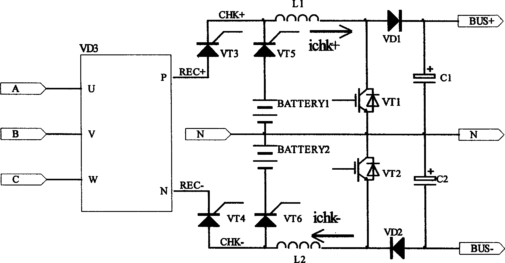
[0012] figure 1 It is the three-phase power factor correction circuit with three-level output proposed in the present invention. VT3 and VT4 generally select power thyristors, and can also be replaced by power relays; VT1, VT2 generally select power field effect transistors or insulated gate bipolar transistors; VD1, VD2 is an ultra-fast recovery power diode; VT5 and VT6 generally choose power thyristors, and can also be replaced by power relays. The connection relationship is: the mains input is a three-phase four-wire system, denoted as A, B, C, N; A, B, C are connected to the three-phase rectifier bridge VD3 input, REC+, REC- are the positive sum of the three-phase rectifier bridge output Negative; REC+ is connected to the A pole of the power switching device VT3, the K pole of VT3 is connected to one end of the boost inductor L1, marked as CHK+, the other end of the boost inductor L1 is connected to the C pole of the boost main VT1 and the boost diode VD1 A The K pole of VD1...


PUM


Abstract

The disclosed correcting circuit and control device possesses features of small size and weight, low complex degree, excellent performance index being suitable to larger power. Circuit providing output in three electrical levels for correcting three-phase power factor includes: triphase rectification bridge VD3, power switch 'VT3, VT4, VT5, VT6', voltage boosting main tube 'VTl, VT2' voltage boosting diodes 'VDl, VD2' etc. Controlling device includes signal sempling unt, logic synthesis unit, core control unit and drive unit.

Description

Technical field [0001] The invention relates to a mains input power factor correction circuit and device, and more particularly to a three-phase power factor correction circuit and a control device thereof. Background technique [0002] The publication number is CN1233104, and the application named "Single-switch Three-phase Power Factor Correction Method and Circuit" discloses a three-phase power factor correction circuit. The circuit is connected with an electronic switch across the output terminal of the rectifier circuit, and the switch is connected with a pulse control signal. Since the circuit has only one switch tube, the control strategy is complicated and the component stress is large, which is not suitable for medium and high power applications. Summary of the invention [0003] The present invention is to overcome the shortcomings in the prior art and provide a three-phase power factor correction circuit and device with th...

Claims


Application Information

Patent Timeline
IPC IPC(8): H02M1/14H02M1/42
CPCY02B70/126Y02B70/10Y02P80/10
Inventor 陈新罗勇武士越
Owner ZTE CORP
Why Eureka
Try Eureka