

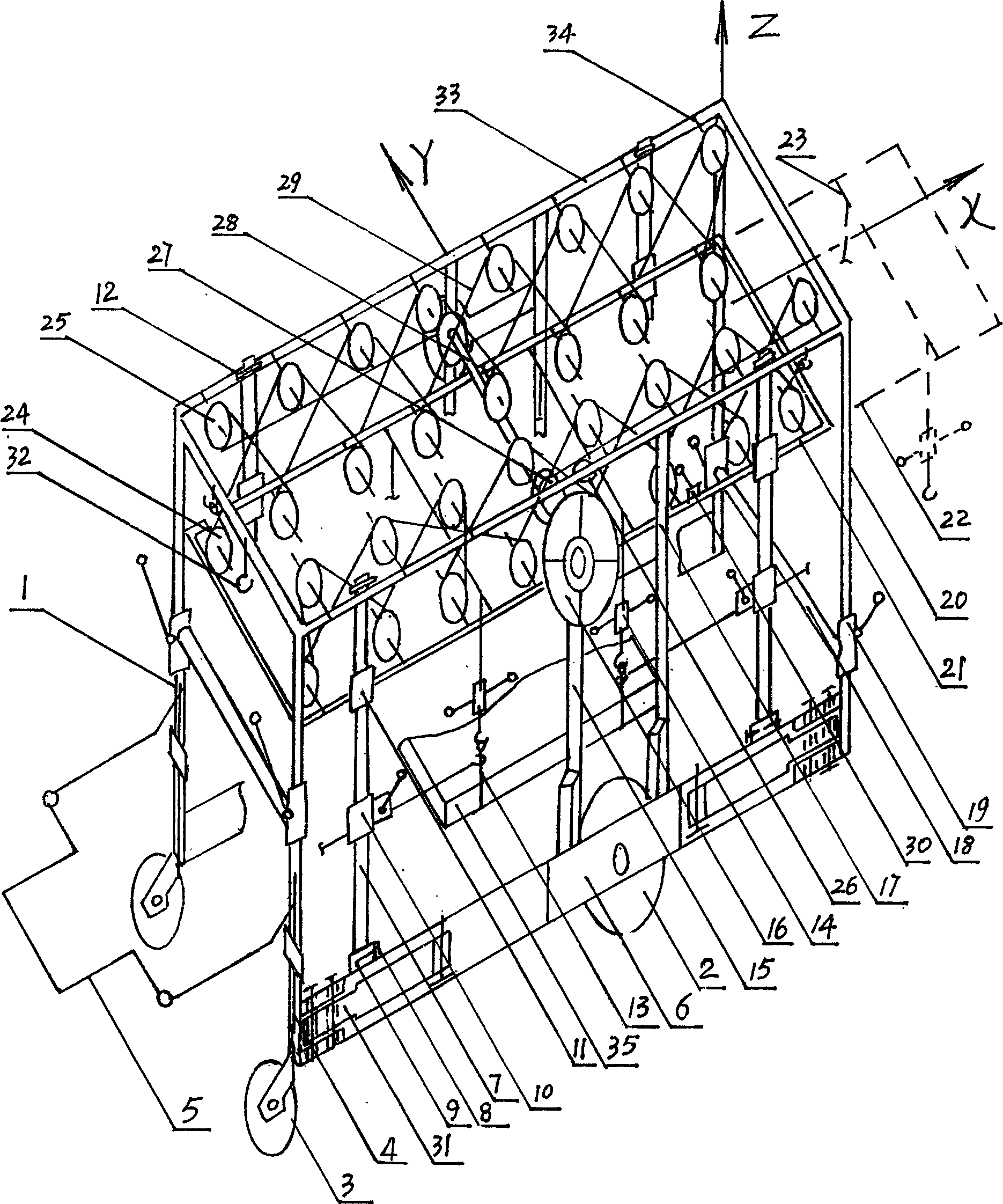
Multifunctional engineering installation vehicle
An installation vehicle and multi-functional technology, applied in the direction of lifting devices, etc., can solve problems such as low installation efficiency, high labor intensity, and difficulty in aligning nozzles, and achieve the effects of improving work efficiency, welding quality, and installation quality
- Summary
- Abstract
- Description
- Claims
- Application Information
AI Technical Summary
Problems solved by technology
Method used
Image


Examples
Embodiment Construction
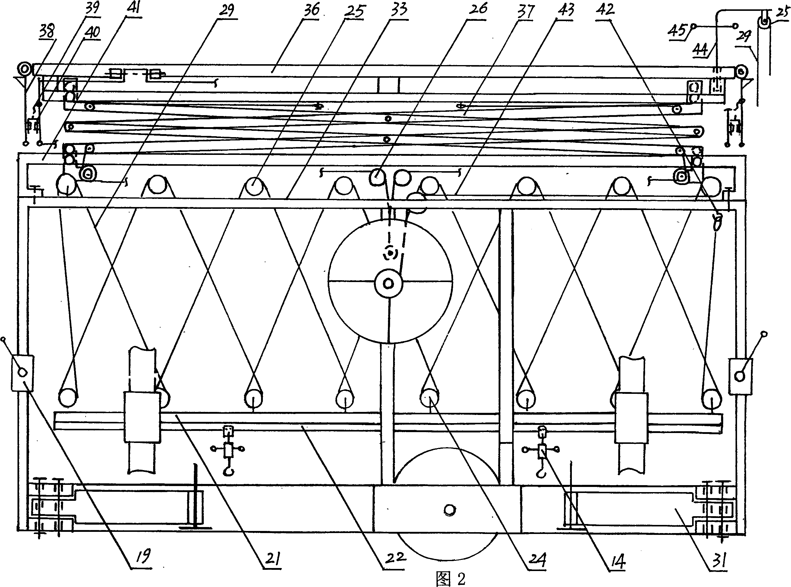
[0077] The present invention will be further described with reference to the accompanying drawings. In Fig. 21, the installation equipment, taking the pump 96 as an example, is transported from the warehouse to the construction site for installation. Use two hoisting ropes 13 to pass through the two ends of the bottom of the pump 96, pull the rope ends upward, and push the car over to the pump Hang the pump 96 directly above the 96, the four rings of the hoisting rope 13 are hooked on the four hooks 95 in the car respectively, and then hook the hoisting rope 13 with four fixed cables 74 on the car, so that the pump 96 can be transported Do not swing, the height and length of the fixed cable 74 can be adjusted through the cable compactor 10, and the height of the cable compactor 10 is determined by the shape of the suspended object. Locked on the guide rod 7, one action locks two objects at the same time, which simplifies operation and saves time. Before the pump 96 is hoisted,...
PUM
 Abstract
Description
Claims
Application Information