Integrated circuit layout plan and buffer plan integrated layout method

A technology of layout planning and integrated circuits, applied to circuits, instruments, electrical components, etc.

Inactive Publication Date: 2004-11-17
TSINGHUA UNIV
View PDF0 Cites 14 Cited by
  • Summary
  • Abstract
  • Description
  • Claims
  • Application Information

AI Technical Summary

Problems solved by technology

Judging from the obtained results, there is sti

Method used


Image

  • Integrated circuit layout plan and buffer plan integrated layout method
  • Integrated circuit layout plan and buffer plan integrated layout method
  • Integrated circuit layout plan and buffer plan integrated layout method

Examples


Embodiment Construction

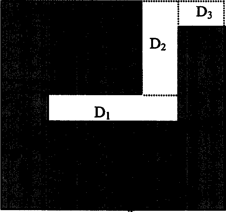
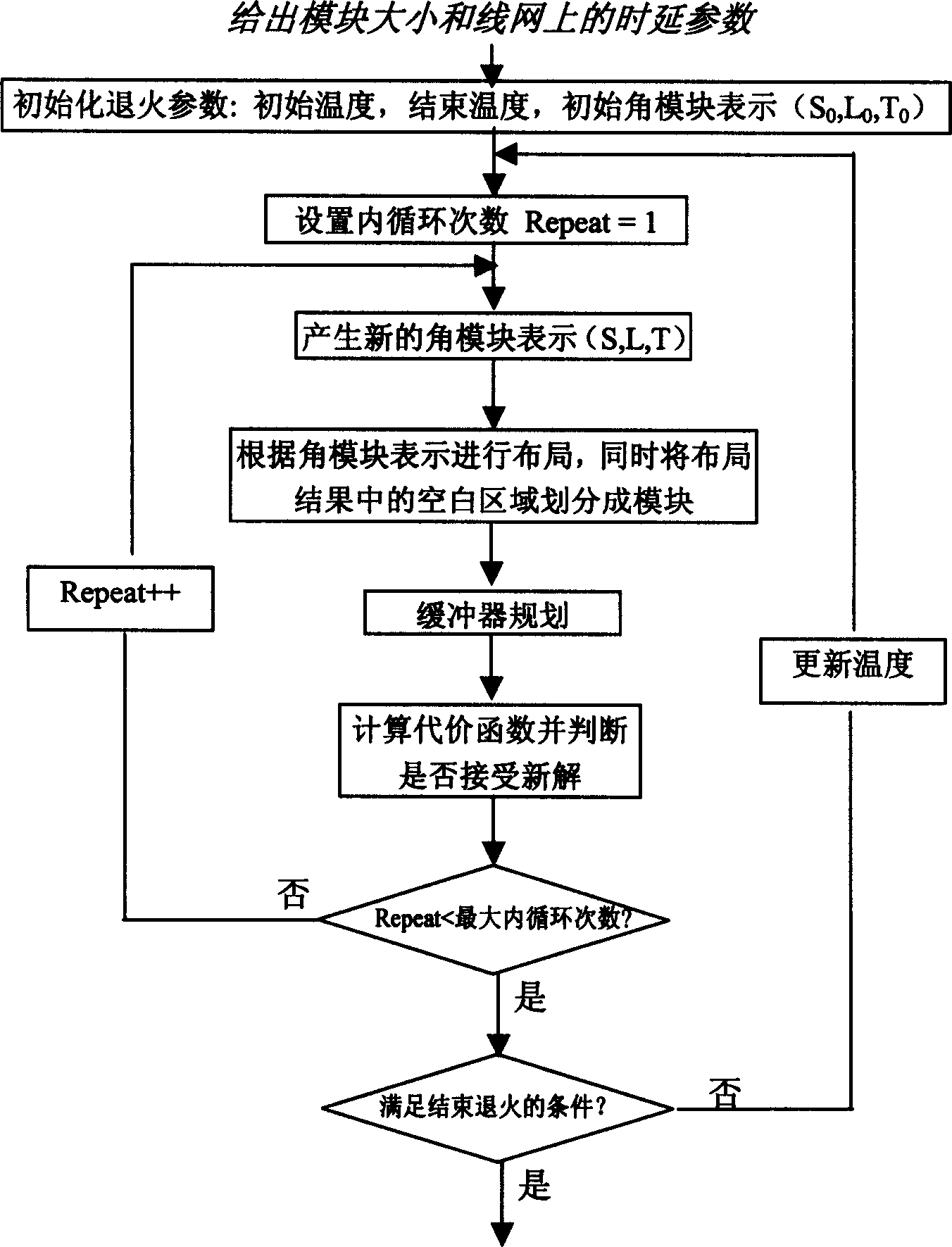
[0108] The present invention can be applied to different layout plans / layout representations based on rectangular division (that is to say, this type of layout representation divides the chip into rectangular areas with a number greater than or equal to the number of modules, and each rectangular area has at most one module) accomplish. This part adopts the layout result represented by the corner module as an example of the present invention, and adopts the Elmore delay model as the model for delay calculation. combine figure 2 A flow chart of floorplanning with integrated buffer insertion planning using the method of the present invention. Table 1 shows the definitions and values ​​of some variables.

[0109] r

Line resistance per unit length (Q / μm)

0.0755

c

Line capacitance per unit length (fF / μm)

0.118

T b

Buffer inherent delay (ps)

36.4

C b

Buffer Input Capacitance (fF)

23.4 ...


PUM


Abstract

The invention is a distribution method integrating the integrated circuit distribution plan and the buffer plan, the invention belongs to computer aided design for integrated circuit field. The character lies in: it introduces the feasible area calculation when the buffer is inserted in, and simplifies the complexity of the buffer distribution through distribution of the blank area in the plan result, the design is carried on pointing to the solution procedure to the simulated quenching by the buffer distribution, the distribution of the buffer is integrated in the solution of the distribution plan. The buffer distribution is leaded in the optimization process of the wiring plan, realizes the optimization to the delay performance.

Description

technical field [0001] The integrated layout method for integrated circuit layout planning and buffer planning belongs to the field of integrated circuit computer-aided design, in particular to the field of BBL (Building Block Layout). Background technique [0002] In the layout of integrated circuits, hierarchical layout design, module reuse technology, a large number of applications of intellectual property modules, the design of system-on-chip especially digital-analog hybrid system-on-chip, and analog circuit device-level layout problems, these problems can all be It boils down to the problem of floorplanning and layout of integrated circuit macro modules, namely Building Block Layout: the layout problem of BBL mode, which has become a current research hotspot. In particular, as the proportion of interconnect lines in the layout becomes larger and larger, the traditional layout planning method ignores the consideration of the layout, resulting in the inability to meet th...

Claims


Application Information

Patent Timeline
IPC IPC(8): G06F17/50H01L21/82
Inventor 洪先龙董社勤蔡懿慈马昱春陈松
Owner TSINGHUA UNIV
Why Eureka
Try Eureka