Constant density printer system

A technology of printers and printing ribbons, applied in printing and other directions, to achieve the effects of eliminating diffusion effects, reducing ink consumption, and avoiding column effects

Inactive Publication Date: 2004-12-01
PRINTRONIX INCORPORATED
View PDF2 Cites 4 Cited by
  • Summary
  • Abstract
  • Description
  • Claims
  • Application Information

AI Technical Summary

Problems solved by technology

However, these ink replenishers typically only replenish ink evenly over the entire ribbon, while other ink replenishers generally reapply ink to the ribbon without detecting areas that need ink
This type of ink replenishment may not produce an even print when a particular portion of the ribbon is used that is darker or lighter than other portions of the ribbon

Method used


Image

  • Constant density printer system
  • Constant density printer system
  • Constant density printer system

Examples


Embodiment Construction

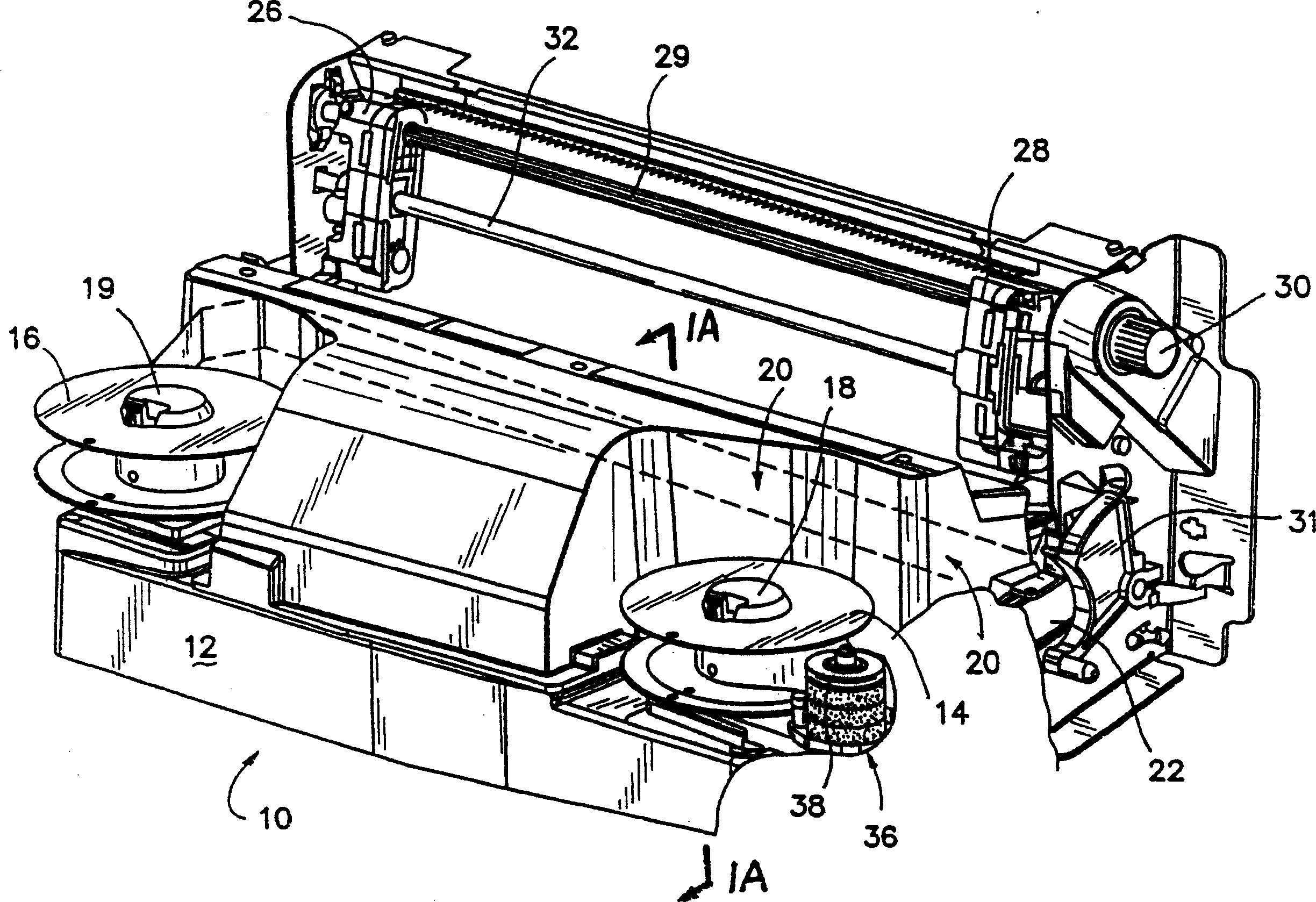
[0064] figure 1 A perspective view of the present invention as an impact line printer 10 is shown. The impact line printer 10 can be installed on a stand, a base, or can be independent in a casing. In this particular instance, the line printer 10 is shown in a configuration with operative elements and without accompanying support material or devices.

[0065] Line matrix printer 10 has a base 12 on which are mounted a pair of ribbon spools 14 and 16 . Ribbon spools 14 and 16 are mounted on hubs or spindles 18 and 19 . Hubs 18 and 19 have resiliently biased catches that tend to secure ribbon spools thereto for drive.

[0066] Ribbon spools 14 and 16 have the path of ribbon 20 shown in phantom. The ribbon 20 traverses at a slight angle in order to allow the ribbon to pass and be struck at different parts thereof as it passes over the hammer set as will be described below.

[0067] A ribbon 20 indicated by a dotted line passing through the inside of the line printer 10 is us...


PUM


Abstract

An ink density closed loop control system for an ink ribbon of an impact line printer having a reservoir roller fluidly connected to a pump and ink supply. A transfer roller can contact the reservoir roller for imparting ink to the ink ribbon. A sensor senses the relative amount of ink on the print ribbon and an electrical drive responsive to the sensor drives the pump for a flow of ink to the one or more channels. The sensor can sense ink on different segments of the ribbon and, with two or more channels in the reservoir roller can distribute ink to two or more segments of the reservoir roller depending upon the ink sensed at a particular segment of the ribbon. A further enhancement of the invention provides a multi-viscosity ink to compensate for changes in ambient temperature conditions.

Description

technical field [0001] This invention relates to an impact printer and, more particularly, to the maintenance of ink content on the print ribbon of such a printer. This is a continuation-in-part of US Patent Application No. 10 / 387,917, filed March 12, 2003, entitled "Constant Density Printer System." Background technique [0002] In the prior art line matrix printer, impact printing can be achieved when the holding force of the hammer is released. When the color ribbon traverses between the hammer and the printing medium, the head of the hammer is urged to hit the ribbon. The other side of the print medium is supported on a hard platen so that the impact from the hammer head leaves ink dots on the print medium. The print media can be paper, labels, multilayer forms, including plastic and combinations of plastic and paper. [0003] The print ribbon traverses at an angle between the single or double row hammers and the media. Each hammer strikes the ribbon at a dedicated a...

Claims


Application Information

Patent Timeline
Patent Type & Authority Applications(China)
IPC IPC(8): B41J2/22
CPCB41J2/22
Inventor 丹尼斯・R・怀特周镇东戈登・B・巴拉斯Y・格兰特・张约翰・W・格默尔约翰・S・金利邱力虎凯文・P・穆尔
Owner PRINTRONIX INCORPORATED
Why Eureka
Try Eureka