
Anti-shock device

A technology for anti-seismic devices and components, which is applied in the directions of anti-seismic, building components, building structures, etc., to achieve the effects of reduced area, reduced construction costs, and easy manufacturing steps

Active Publication Date: 2004-12-01
NIPPON STEEL & SUMIKIN ENG CO LTD
View PDF3 Cites 18 Cited by
  • Summary
  • Abstract
  • Description
  • Claims
  • Application Information

AI Technical Summary

Problems solved by technology

[0006] In addition, also in JP Unexamined Patent Publication No. 60-223576 (Patent Document 4), a U-shaped anti-seismic device is described, but this document does not address the performance of the anti-seismic device when horizontal deformation occurs in any direction of the earthquake. directional description

Method used


Image

  • Anti-shock device
  • Anti-shock device
  • Anti-shock device

Examples


no. 1 Embodiment

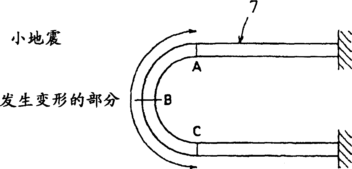
[0128] Fig. 6 shows an embodiment of the present invention. In this embodiment, an attenuation mechanism 6 is provided between the upper structure 2 and the bottom structure 3 interposed with the isolator 1 . The attenuation mechanism 6 adopts a plurality of curved parts 7 formed from elastic-plastic materials into a substantially U-shape as shown in FIG. In this way, two curved members are combined to form a set, and a plurality of sets of such sets are used. As shown in FIG. 9, the curved member 7 is, for example, made of elastoplastic material, and a steel material with a rectangular cross-section of 25 mm in length and 50 mm in width is formed into a curved shape. After forming, if necessary, heat treatment is performed to remove residual deformation. The installation part 8 at one end of the corresponding curved part 7 is fixed on the upper structure 2 , and the installation part 9 at the other end is fixed on the bottom structure 3 .

[0129] In addition, when the atte...

no. 2 Embodiment

[0146] Fig. 18 shows an embodiment of the present invention. This embodiment is the following anti-seismic device, wherein, on the outer periphery of the isolator 1 sandwiched between the upper structure 2 and the bottom structure 3, a curved member 7 constituting the damping mechanism 6 is provided, and the isolator 1 and the curved member 7 set integrally. As shown in Figure 19, on the outer periphery of the connecting plate 14 connecting the isolator 1, the isolator with the upper structure 2 and the bottom structure 3, two or more of them are curved and are formed of elastic-plastic materials. Components 7 are circular as shown in Figure 20 and Figure 21, arranged at equiangular intervals, and combined in a lantern shape, or as shown in Figure 22 and Figure 23, two curved components 7 are line-symmetric Combined in different ways, thus forming a group, and the multiple groups of components are arranged on the outer periphery of the isolator 1 . In the process of installi...


PUM


Abstract

To provide a seismic isolator, improved in capability of absorbing the energy of an earthquake, and easily manufactured and constructed at a low price by disposing a damping mechanism formed of a curved member and an isolator between an upper structure and a lower structure. In this seismic isolator, the isolator 1 and both end parts 8, 9 of two or more curved members 7 formed of elasto-plastic material constituting a damping mechanism are disposed between an upper structure 2 and a lower structure 3, and fixed to the upper structure 2 and the lower structure 3. The curved member 7 is formed to draw a circle like a lantern by combination of two or more members or two or more sets of a pair of two curved members opposite to each other symmetrically, and disposed in the periphery of the isolator 1. Thus, the curved member 7 is plastically deformed to absorb the energy of an earthquake.(C)2005,JPO&NCIPI.

Description

technical field [0001] The present invention relates to a plastic hysteresis type anti-seismic device installed between a superstructure and a bottom structure to attenuate the vibration of the superstructure during an earthquake and absorb seismic energy. Background technique [0002] In the past, various types of anti-seismic devices have been proposed by changing the shape of the parts as plastic hysteresis type anti-seismic devices installed between the building structure and the superstructure and substructure such as the foundation supporting the structure. [0003] For example, JP Patent Publication No. 2-62671 (Patent Document 1) discloses a device in which an anti-seismic device is formed in a straight rod shape and each end is fixed to an upper and lower structure. In addition, JP Patent Publication No. 2-59262 (Patent Document 2) discloses an anti-vibration device formed into a ring shape. [0004] For example, JP-A-2-194233 (Patent Document 3) discloses a device...

Claims


Application Information

Patent Timeline
IPC IPC(8): E04B1/36E04B1/98E04H9/02F16F15/02F16F15/04
Inventor 佐伯英一郎渡边厚铃木一弁
Owner NIPPON STEEL & SUMIKIN ENG CO LTD
Learn More