Method for in situ construction of a wind power plant

A technology for wind power generation equipment and on-site assembly, which is applied in the directions of wind turbine components, wind turbine assembly, wind power generation, etc., and can solve problems such as reducing the service life of components and damage.

Inactive Publication Date: 2004-12-01
阿洛伊斯沃本
View PDF0 Cites 9 Cited by
  • Summary
  • Abstract
  • Description
  • Claims
  • Application Information

AI Technical Summary

Problems solved by technology

The torque generated in that situation can cause damage or reduce the service life of components, especially the service life of mechanical drive trains

Method used


Image

  • Method for in situ construction of a wind power plant
  • Method for in situ construction of a wind power plant
  • Method for in situ construction of a wind power plant

Examples


Embodiment Construction

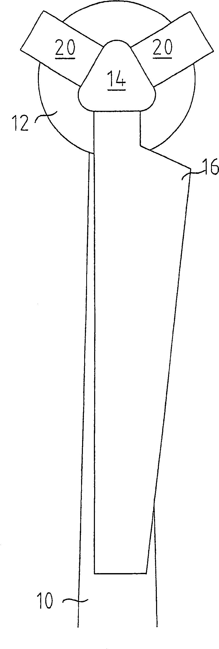
[0021] figure 1 The upper part of a steel tower 10 is shown, at the top of which a nacelle 12 is arranged, in which are arranged mechanical brackets for accommodating all mechanically moving parts of the wind power plant. Arranged centrally in the nacelle 12 (of the mechanical carrier) is a rotor hub 14 , on which rotor blades 16 can be mounted via a flange connection. One of the rotor blades 16 is shown in the installed position.

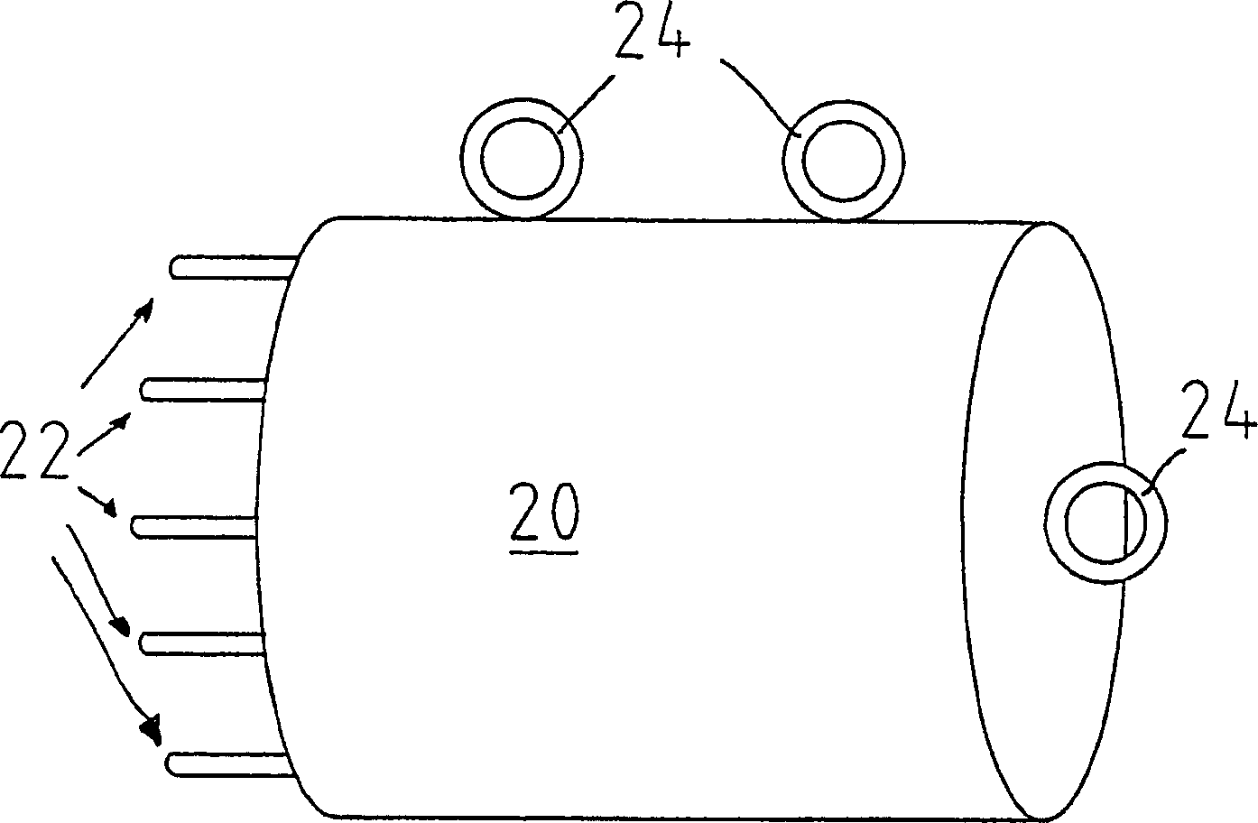
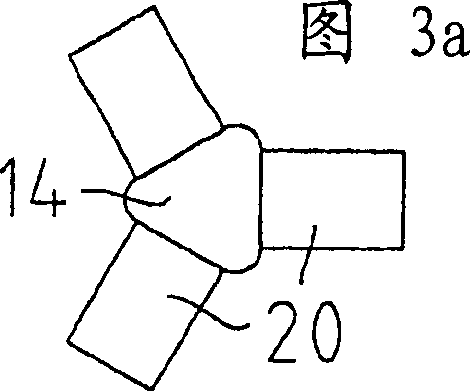
[0022] Arranged on the holding flange connection is a counterweight 20 , which imposes on the rotor hub 14 the load conditions that occur when the three rotor blades 16 are mounted in place. In this case, the torque produced is zero. In this way, the rotor hub 14 can be turned into a desired position. One of the counterweights 20 can then be removed and replaced by a rotor blade 16 . As a result, the load conditions remain unchanged, so that a further rotation and replacement of the remaining counterweight 20 by a rotor blade 16 does not presen...


PUM


Abstract

One aspect of the present invention concerns a process for mounting rotor blades to a rotor hub of a wind power installation in situ. In order to avoid high torques in the mechanical train of the wind power installation in the operation of mounting the rotor blades, a process according to one aspect of the invention includes the following steps: mounting a weight to at least one flange of the rotor hub; mounting the rotor blade in the installation situation; rotating the rotor hub into a predeterminable position; and exchanging the weight arranged on the flange of the rotor hub for a rotor blade by removing the weight and then mounting the rotor blade to the rotor hub.

Description

technical field [0001] The invention relates to a method for on-site mounting of rotor blades on a rotor hub of a wind power plant. Background technique [0002] This method is already known and avoids the problems that arise when fitting the rotor on the rotor hub on the ground and that are associated with subsequent work steps when installing the rotor on the wind power plant. For example, such an assembly process is described in Windkraft-Journal, edition 1 / 2000, page 13, January 2000. [0003] As can be seen from the description, first the gondola with the rotor hub is mounted on top of the tower. The rotor blades are then lifted by a crane and assembled on site to the rotor hub. [0004] However, the known method described above has the disadvantage that after the installation of the first rotor blade there is already a considerable unbalance due to the one-sided load of the blade, and when the rotor hub is further rotated to the installation position of the next blad...

Claims


Application Information

Patent Timeline
Patent Type & Authority Applications(China)
IPC IPC(8): F03D11/04F03D1/06
CPCF03D1/0658F03D1/001Y02E10/728Y02E10/721F03D13/10F03D1/06Y02E10/72
Inventor 阿洛伊斯·沃本
Owner 阿洛伊斯沃本
Why Eureka
Try Eureka