Method for measuring radio communication system propagation delay

A wireless communication system and propagation delay technology, applied in the field of wireless communication systems, can solve problems such as inaccurate estimation of propagation delay, achieve the effect of increasing coverage radius and improving accuracy

Inactive Publication Date: 2004-12-15
ZTE CORP
View PDF1 Cites 14 Cited by
  • Summary
  • Abstract
  • Description
  • Claims
  • Application Information

AI Technical Summary

Problems solved by technology

[0005] The purpose of the present invention is to provide a method for measuring the propagation delay of a wireless communication system, which solves the tech

Method used


Image

  • Method for measuring radio communication system propagation delay
  • Method for measuring radio communication system propagation delay
  • Method for measuring radio communication system propagation delay

Examples


Embodiment 1

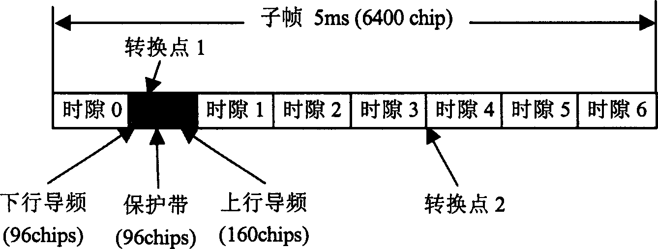
[0050] For mobile communication systems that use TDD (Time Division Duplex) as a duplex communication method, such as TD-SCDMA, PHS (Personal Handset System), etc., the downlink and uplink work on the same frequency band, but up and down in a certain way This frequency band is time-shared between rows. image 3It is a time-sharing mode between the uplink and downlink of a subframe in the TD-SCDMA system. A subframe is the minimum time interval for a burst transmission. Slot 0 is generally a common channel, and the downlink pilot is sent by the Node B to the UE, so that the UE can synchronize with the system according to the received downlink pilot. The guard band GP is a guard period to prevent overlapping of uplink pilots and downlink pilots. Time slot 1--time slot 6 are user time slots for transmitting voice or data services. When the system transmission switches between uplink and downlink, it is called a transition point. There are two transitions between uplink and down...

Embodiment 2

[0062] In the IS95A system, the access signal of the mobile station is often searched through a fixed window. Sometimes, because the mobile station is too far away from the base station, its access signal falls outside the search window of the base station, so it cannot be found by the base station, resulting in failure to access the system.

[0063] By transmitting the propagation model of the pilot channel of the current base station in the synchronous channel of the base station, the mobile station calculates the distance and propagation delay from the base station by measuring the power of the pilot channel, and transmits a certain time in advance, which can Let the long-distance mobile station signal fall within the search window of the base station. The implementation steps are as follows:

[0064] In the first step, in the network planning of the IS95A system, use the existing propagation model, or obtain the propagation model of each Node B in the form of formula (5) ...


PUM


Abstract

This invention discloses a method for measuring propagation delay of radio communication system, among which, the devolved system is composed of a base station and a terminal. This invention includes the following steps: calculating or fitting to get the radio transmission loss mode of a base station which sends the transmission loss mode by broad cast to the regions covered by it, the terminal gets, the transmission loss mode of the base station by demodulation and measures the received power to compute its distance to the base station and air signal transmission delay according to the received power and the transmission loss model of the base station. This invention increase the accuracy of computing transmission delay time by the terminal so as to increase the cover radius of the base station by emitting before hands locate terminals accurately.

Description

technical field [0001] The invention relates to a wireless communication system, especially a method for measuring wireless propagation delay in a mobile communication system. Background technique [0002] The structure of the mobile communication system involved in the present invention is as attached figure 1 As shown, it includes at least one CN (core network), one RNC (radio access network controller), one Node B (Node B), which is generally called a base station, and one UE (terminal). [0003] Between the Node B and the UE, there is a propagation delay, and this propagation delay increases as the distance between the UE and the Node B increases. Due to the propagation delay, when the UE's signal reaches the Node B, a propagation delay of 2 times occurs. [0004] The Chinese Patent Office has published a patent entitled "Equipment and Method for Measuring Propagation Delay in Narrowband Time Division Duplex Code Division Multiple Access Mobile Communication System" wi...

Claims


Application Information

Patent Timeline
IPC IPC(8): H04B17/40
Inventor 姚春波吴岩巍
Owner ZTE CORP
Why Eureka
Try Eureka