Multifunction tridimension displacement laser interference measuring system

A technology of laser interferometry and measurement system, applied in the field of three-dimensional displacement laser interferometry system, can solve the problems of simultaneous measurement, moiré interferometry and electronic speckle interferometry, etc., and achieve the effect of compact structure and convenient use

Inactive Publication Date: 2004-12-22
TSINGHUA UNIV
1 Cites 45 Cited by

AI-Extracted Technical Summary

Problems solved by technology

However, the first two devices are only suitable for moiré interferometry and can only realize the measurement of two displacement fields u and v in the plane, while the latter two are only suitable for speckle in...

Method used

Six-dimensional adjustment load frame 5 (as shown in Figure 4) is by loading frame 34, lifting translation platform 35 (model GCM-150104M), precision translation platform 36 (model GCM-125301AM), in-plane rotary table 37 (model: GCM -1101M), pitching platform 38 (model: GCM-190) and vertical plane in-plane rotating platform 39 (model: GCM-1101M) consists of six parts. The rotary platform 39 in the vertical plane is fixed on the pitch platform 38 by screws; the precision translation platform 36 is connected on the rotary platform 39 in the vertical plane through a ball steel wire gap-free guide rail; The translation platform 36 is connected; the in-plane rotation platform 37 is connected with the lifting translation platform 35 through a slider mechanism and a rack and pinion locking mechanism; the loading frame 34 is fixed on the in-plane rotation platform 37 by screws. Pitch table 38 links to each other with workbench base plate by adjusting screw (lower end is spherical) and adjusting screw rod. Rotate the screw rod 46 to change the pitch angle of the pitch table; the rotary table 39 in the vertical plane is connected to the pitch table 38 by fastening screws, and the function of the rotary table in the vertical plane is to precisely adjust the rotation in the vertical plane of the test piece to achieve zero adjustment. field and eliminate rigid body rotation during load application. The precision translation stage 36 is connected to the rotary table 39 in the vertical plane through the ball steel wire gapless guide rail, and can be driven by the micrometer screw 47 to provide linear motion for the translation...

Abstract

The measuring system is composed of laser, image collection camera system, spectrum coupler, 3D interference optical system, and 6D adjustable loading frame. The measuring system provides functions of real time measurement in u, v, w three displacement fields with high accuracy in sensitivity of wavelength magnitude, possessing two measuring modes: gradation interference and electronic speckle interference. Adjustment in six degrees of freedom is realized by 6D adjustable loading frame so as to implement loading experiments of one-way pulling and pressing, and bending at three points providing features of easy of use, compact structure and high precision. Moreover, there is phase shift system. Measuring precision reaches to nano magnitude when phase shift technique is applied.

Application Domain

Technology Topic

Laser interferencePhysics +7

Image

  • Multifunction tridimension displacement laser interference measuring system
  • Multifunction tridimension displacement laser interference measuring system
  • Multifunction tridimension displacement laser interference measuring system

Examples

  • Experimental program(1)
  • Effect test(1)

Example Embodiment

[0021] Further illustrate concrete structure and embodiment of the present invention below in conjunction with accompanying drawing:
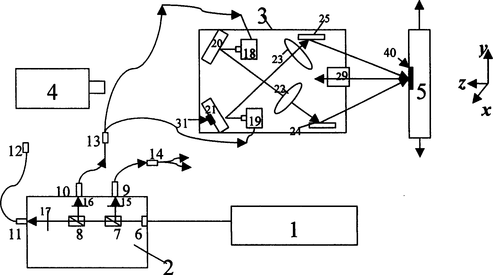
[0022] like figure 1 As shown, the multifunctional three-dimensional displacement laser interferometry system of the present invention is mainly composed of a laser 1, a light splitting coupler 2 that can control light splitting to form three displacement fields, a three-dimensional interference optical path system 3, an image acquisition camera system 4, and a six-dimensional The adjustment load frame consists of 5 components, all of which are installed on a worktable. The three-dimensional interferometric optical system 3 is integrated in the dark box and fixed on the workbench through three lifting supports to make the system miniaturized. The laser 1 and the optical coupler 2 are fixed on the workbench by fastening screws, and are located on the same side of the three-dimensional interference optical system 3 . The six-dimensional adjustment load frame 5 and the image acquisition camera system 4 are respectively installed on the front and rear sides of the three-dimensional interference optical path system, and they can slide linearly on the dovetail groove guide rail on the workbench to change the front and rear orientations.
[0023] The light splitting coupler 2 of the present invention contains two beam splitters 7, 8 and switch controllers 15, 16, 17 that divide the light emitted by the laser 1 into three paths, wherein the optical path for measuring u field displacement passes through the beam splitter 7 in turn , the switch controller 15, and the optical fiber beam splitter 14, divide into two paths and enter the laser coupler 41 and 42 in the three-dimensional interference optical path system 3 respectively, collimate through the collimating mirrors 26 and 27, and reflect through the mirrors 44 and 45 Then it is incident on the surface of the test piece 40; the optical path for measuring the v-field displacement passes through the beam splitter 8, the switch controller 16 and the optical fiber beam splitter 13 respectively, and then respectively enters the laser couplers 18 and 19 in the three-dimensional interference optical path system 3, and passes through the mirror 20, 21 and collimating mirrors 22, 23 are collimated and then reflected by mirrors 24, 25 and incident on the surface of test piece 40; the optical path for measuring w-field displacement is incident into the three-dimensional interference optical system through switch 17 and fiber coupler 12 in turn After the collimating mirror 28, it is divided into two beams of light after the dichroic prism 29, wherein a beam of light directly passes through the dichroic prism 29 and is incident on the reflector 30, and then reaches the image acquisition camera system 4 through the dichroic prism 29 after reflection; A light beam is reflected by the dichroic prism 29 and reaches the test piece 40 , and after being reflected by the grating on the surface of the test piece, passes through the dichroic prism 29 to reach the image acquisition camera system 4 .
[0024] The optical devices in the optical coupler 2, i.e. the beam splitters 7, 8, the fiber couplers 9, 10, 11, 12, the fiber beam splitters 13, 14 and the switch controllers 15, 16, 17 are all packaged in a box , and a filter hole 6 is provided at the entrance of the laser beam of the box, and the box is fixed on the worktable by screws. The beam emitted by the laser 1 is divided into five optical fiber beams after passing through the optical coupler 2 . Among them, the beam passes through the beam splitter 7, the fiber coupler 9, and the fiber beam splitter 14 to form a displacement u-field measurement double beam, and the beam passes through the beam splitter 8, the fiber coupler 10, and the fiber beam splitter 13 to form a displacement v-field measurement double beam . After passing through the beam splitter 8, the fiber coupler 11 and the fiber coupler 12, the out-of-plane displacement w field measurement beam is formed. Switch controllers 15, 16, and 17 are arranged in the light-splitting coupler, which can respectively control the use of three displacement field measurement optical paths of u, v, and w.
[0025] Optical devices in the three-dimensional interference optical system 3, i.e. laser couplers 18, 19, 41, 42, 12, mirrors 20, 21, 24, 25, 44, 45, 30, collimating lenses 22, 23, 26, 27 , 28, and beam splitting prism 29 are all encapsulated in a dark box. Wherein laser coupler 18, reflecting mirror 20,25, and collimating lens 23 are fixed on the top in the dark box, and laser coupler 19, reflecting mirror 21,24, and Collimating lens 22, these optics are used to measure v-field displacement (such as figure 1 shown). A laser coupler 42, a reflector 45 and a collimator lens 27 are fixed on the left side wall in the box, and a laser coupler 41, a reflector 44, and a collimator lens 26 are respectively arranged on symmetrical positions on the right side wall. Used to measure u-field displacements (such as figure 2 shown); on the front and rear centerlines of the dark box, a laser coupler 12, a collimator lens 28, a beam splitting prism 29, and a mirror 30 are installed in sequence, and these optical elements are used to measure the displacement of the w field (such as image 3 shown).
[0026]Six-dimensional adjustment load frame 5 (such as Figure 4 ) consists of a loading frame 34, a lifting translation table 35 (model GCM-150104M), a precision translation table 36 (model GCM-125301AM), an in-plane rotation table 37 (model: GCM-1101M), and a tilting table 38 (model: GCM-190 ) and a vertical in-plane rotary table 39 (model: GCM-1101M) consisting of six parts. The rotary platform 39 in the vertical plane is fixed on the pitch platform 38 by screws; the precision translation platform 36 is connected on the rotary platform 39 in the vertical plane through a ball steel wire gap-free guide rail; The translation platform 36 is connected; the in-plane rotation platform 37 is connected with the lifting translation platform 35 through a slider mechanism and a rack and pinion locking mechanism; the loading frame 34 is fixed on the in-plane rotation platform 37 by screws. Pitch table 38 links to each other with workbench base plate by adjusting screw (lower end is spherical) and adjusting screw rod. Rotate the screw rod 46 to change the pitch angle of the pitch table; the rotary table 39 in the vertical plane is connected to the pitch table 38 by fastening screws, and the function of the rotary table in the vertical plane is to precisely adjust the rotation in the vertical plane of the test piece to achieve zero adjustment. field and eliminate rigid body rotation during load application. The precision translation stage 36 is connected to the rotary table 39 in the vertical plane through the ball steel wire gapless guide rail, and can be driven by the micrometer screw 47 to provide linear motion for the translation stage, and the displacement resolution of the movement can reach 0.001mm. The lifting translation platform 35 is connected with the precision translation platform 36 by means of the dovetail guide rail 48, and the translation platform can slide forward and backward along the linear guide rail. The in-plane rotating table 37 is connected with the smooth grooved guide rail on the lifting translation table 35 through the slider mechanism, and the rack and pinion on the guide rail realize the lifting and translation (relative to the test piece) forward and backward, with long moving stroke and fast speed , stable movement, etc., with an accuracy of 0.1mm, it is convenient to adjust the up and down, front and back, and left and right movements of the specimen to achieve the purpose of centering, and to meet the requirements of moiré interference on the position adjustment of the specimen. The micrometer screw 49 on the rotary table 37 can provide 360° manual rotation, so that the test piece can be precisely and finely adjusted in the angle of the tested surface, with an accuracy of up to ±10″, and can easily apply carrier waves (or eliminate carrier waves) , zero field and eliminate the rigid body rotation produced in the process of applying load. Loading frame 34 is fixed on the in-plane rotary table 37 by fastening screws. The screw rod 50 of linear motion is connected at the specimen upper end, and screw rod is fixed on the top of loading frame, The lower end is connected with a force sensor 51. The loading frame can provide experiments such as one-way tension and compression, three-point bending, and pure bending.
[0027] The image acquisition camera system 4 is used to acquire moiré images in real time. It consists of a CCD and a three-degree-of-freedom fixed bracket with horizontal and vertical directions. The images collected by the CCD are directly input into the computer for data processing.

PUM

no PUM

Description & Claims & Application Information

We can also present the details of the Description, Claims and Application information to help users get a comprehensive understanding of the technical details of the patent, such as background art, summary of invention, brief description of drawings, description of embodiments, and other original content. On the other hand, users can also determine the specific scope of protection of the technology through the list of claims; as well as understand the changes in the life cycle of the technology with the presentation of the patent timeline. Login to view more.

Similar technology patents

Adaptive canceller for frequency reuse systems

ActiveUS6859641B2Effective and efficient mannerEasy to useRadio transmissionTransmission noise suppressionSignal of interestSatellite
Owner:RAYTHEON APPLIED SIGNAL TECH

Utilization of podcasts on portable media devices

InactiveUS20060265637A1Easy to useDigital data information retrievalUsing non-detectable carrier informationMediaFLOMetadata
Owner:APPLE INC

Reconfigurable measurement system utilizing a programmable hardware element and fixed hardware resources

InactiveUS20030163298A1Easy to useSimplyError detection/correctionMeasurement arrangements for variableProgrammable hardwareComputer hardware
Owner:NATIONAL INSTRUMENTS

Classification and recommendation of technical efficacy words

  • Easy to use
  • Compact structure

Laser assisted total joint arthroplasty

InactiveUS20090234360A1Easy to useNon-surgical orthopedic devicesSurgical sawsLaser assistedLaser guidance
Owner:ALEXANDER VLADIMIR

System, method, and apparatus for settlement for participation in an electric power grid

ActiveUS8583520B1Communication securityEasy to useLevel controlCoin-freed apparatusNetwork managementGrid operator
Owner:CAUSAM ENERGY INC
Why Eureka
Try Eureka