Wind motor

A technology of wind-powered engines and generators, applied in the direction of wind-powered engines, engines, wind-powered generator components, etc., which can solve the problems of hindering the operation of wind rotors and the low utilization rate of wind energy of wind-powered machines, and achieve the effects of eliminating resistance and resisting strong winds

Inactive Publication Date: 2004-12-29
徐传富
View PDF0 Cites 9 Cited by
  • Summary
  • Abstract
  • Description
  • Claims
  • Application Information

AI Technical Summary

Problems solved by technology

Since the convex surface of the semi-circular barrel rotates against the wind direction when facing the wind, which h

Method used


Image

  • Wind motor
  • Wind motor
  • Wind motor

Examples


Embodiment Construction

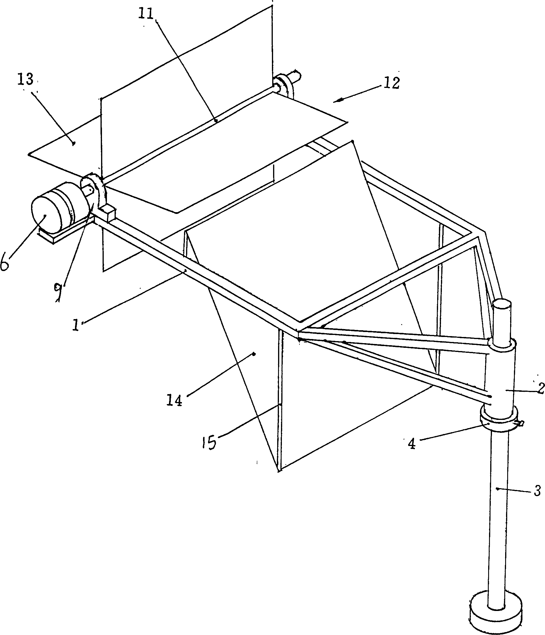
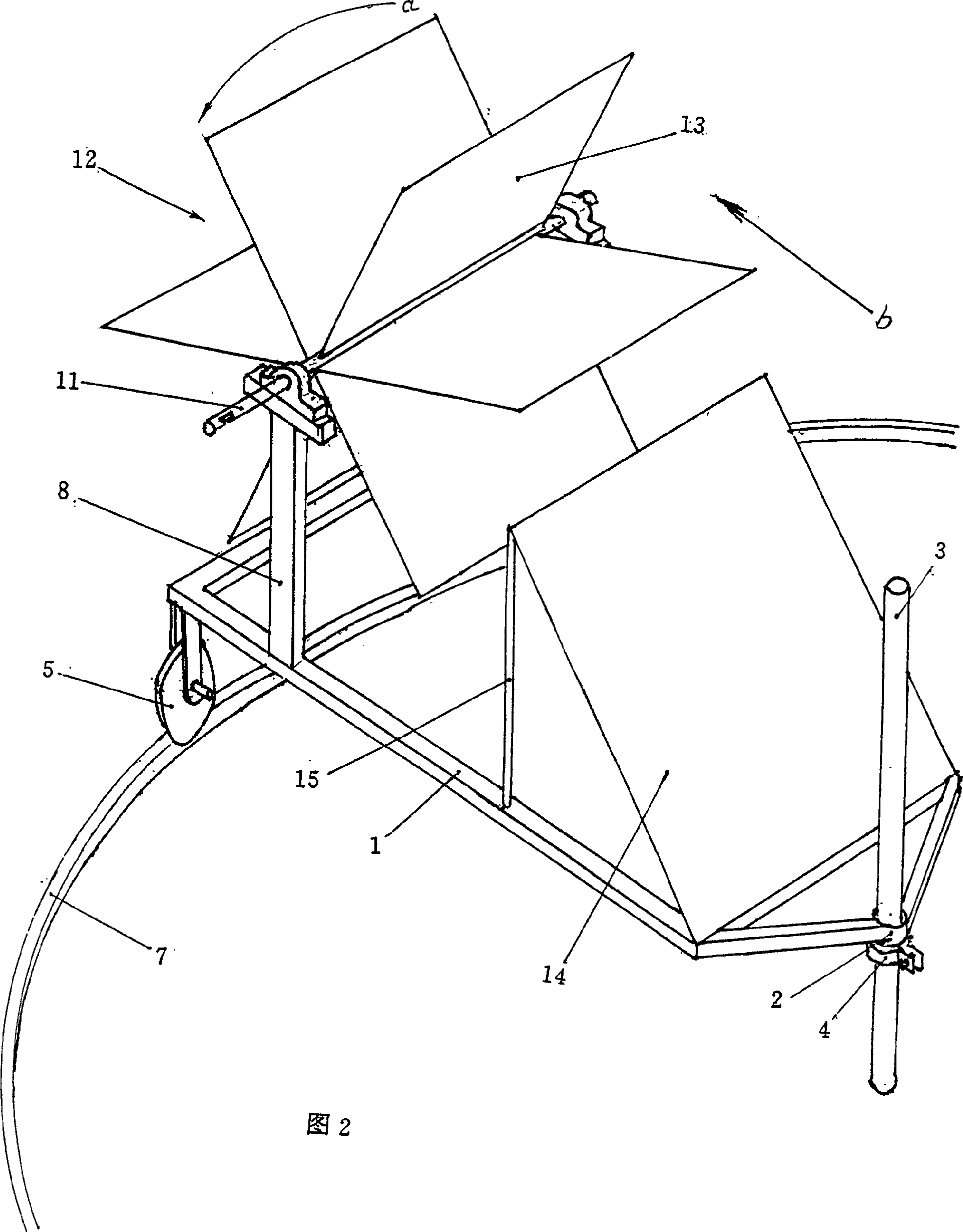
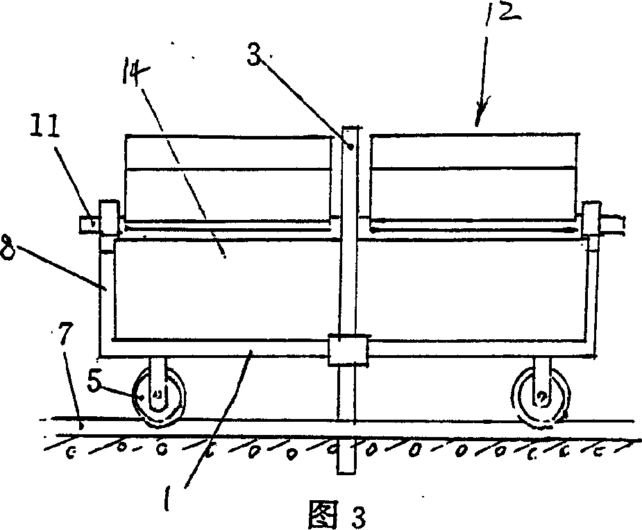
[0028] figure 1 It is a perspective view of the first embodiment of the wind power engine of the present invention. One end of the vehicle frame 1 is provided with a shaft 2, which is sleeved on the outside of the mast 3, and a positioning ring 4 is also provided outside the mast 3, so that the shaft 2 is positioned at a certain height of the mast 3, so that it does not slide up and down, and the inner wall of the shaft 2 It is a smooth drum, and the mast 3 is a cylinder with a smooth outer wall. The shaft 2 is set outside the mast 3 and cooperates with it, so that the shaft 2 can rotate freely around the mast 3; The two ends of the wind wheel shaft 11 pass through the bearings in the bearing seat 9 located on the vehicle frame 1, and 4 rigid sail blades 13 that are symmetrical to the wind wheel shaft and integrated into one body are arranged around the wind wheel shaft 11. Between the wind wheel 12 and the mast 3 is provided with a guide sail 14, the side of the guide sail 1...


PUM


Abstract

The wind engine has frame, shaft, mast, wheels, wind tower on the frame, wind wheel with wind wheel shaft penetrating the bearing in the bearing seat on the wind tower, wind guiding sail set between the wind wheel and the mast, and wind converging sail to converge wind in relatively large range into the sail blade. The wind engine can obtain great wind energy to drive generator to produce electricity, and has low cost and great economic utility.

Description

technical field [0001] The invention relates to a device for utilizing wind energy, in particular to a wind power engine. Background technique [0002] Wind energy is an inexhaustible, non-polluting and renewable new energy source. In order to develop and utilize wind energy, people have invested a large amount of manpower and material resources to design and manufacture various wind power engines. [0003] In recent decades, people have invented a kind of S wheel type wind turbine again. The S-wheel wind turbine is recorded on page 84 of the book "Clean New Energy - Energy in the 21st Century", edited by Hu Chengchun. Beijing: Science and Technology Literature Publishing House, 1995.7. The S-wheel wind power was invented by the Finn Savonius. This is a drag-type wind turbine, which is composed of two semi-circular barrels (or sail blades) connected symmetrically with a vertical axis. In order to obtain greater power, multiple wind rotors can b...

Claims


Application Information

Patent Timeline
IPC IPC(8): F03D3/04F03D13/20
CPCY02E10/72Y02E10/74
Inventor 徐传富
Owner 徐传富
Why Eureka
Try Eureka