Measuring device for concrete shrinkage and stress

A measuring device, concrete technology, applied in the direction of material inspection products, etc., to achieve the effect of simple structure, small elastic deformation and small volume

Inactive Publication Date: 2004-12-29
HARBIN INST OF TECH
View PDF0 Cites 22 Cited by
  • Summary
  • Abstract
  • Description
  • Claims
  • Application Information

AI Technical Summary

Problems solved by technology

[0002] The shrinkage and deformation of concrete and the stress generated are very important parameters, especially the measurement of the early shrinkage of high performance concrete and the accurate determination of the internal

Method used


Image

  • Measuring device for concrete shrinkage and stress
  • Measuring device for concrete shrinkage and stress
  • Measuring device for concrete shrinkage and stress

Examples


Embodiment Construction

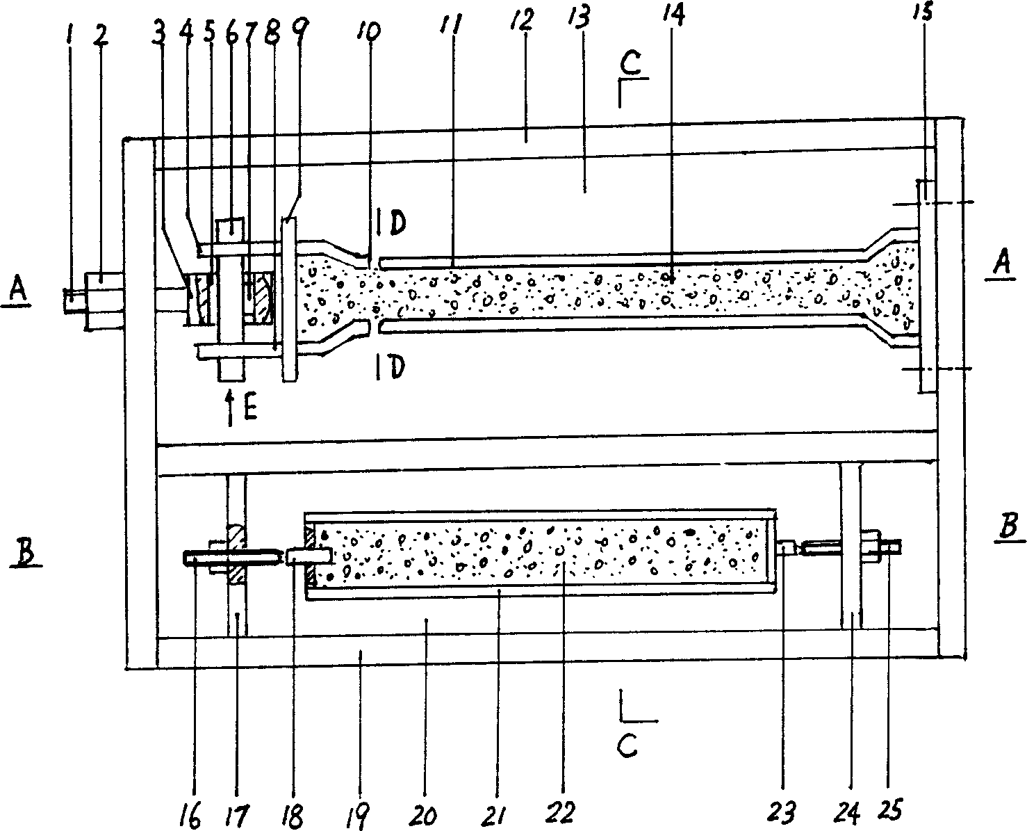
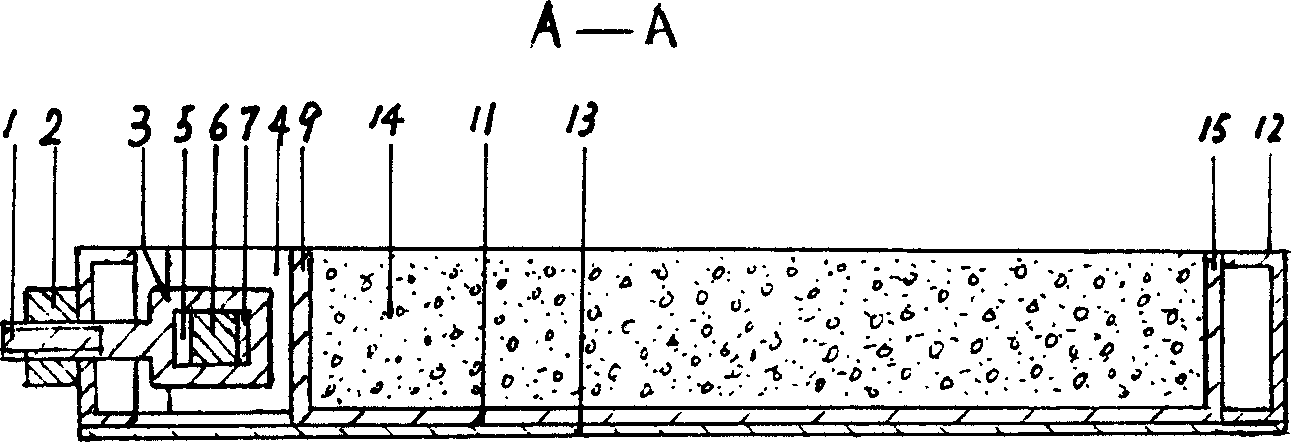
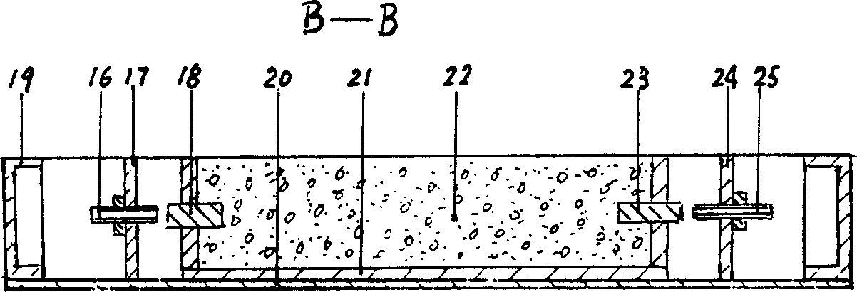
[0014] Such as figure 1 As shown, two rectangular frames (12) (19) are welded by channel steel, steel plates (13) (20) are welded under the frame, and the mold (11) and mold (11) for measuring the concrete stress are placed in the frame (12) It is a rectangular groove made of steel plate. The cross section at both ends is larger than the middle, and it is trapezoidal. There are open grooves (10) on both sides of one end of the mold. One end of the mold (11) is fastened to the frame (12) with screws. (11) The other end of the blocking plate (9) welded two steel plates (4) (8), the steel plate (4) (8) has a square hole, one end of the screw (1) is a rectangular steel block (3), ( 3) There is a rectangular hole (5) inside. The square steel column (6) penetrates the square hole of the steel plate (4) (8) and the rectangular hole (5) at one end of the screw (1). The quartz load cell (7) is installed Between the rectangular hole (5) and the square steel column (6). The screw (1) passes...


PUM


Abstract

The present invention is one kind of automatic continuous concrete contraction and stress measurer. On one test stage, there are two concrete molds, one for measuring stress and the other for measuring contraction. The mold for measuring concrete stress has one end fastened to the frame and the other end connected to the frame with screw and nut, and the other end of the screw has dynamometric quartz sensor connected with output signal fed to instrument or microcomputer. The mold for measuring concrete contraction has central hole in the two ends for the small steel column pre-buried inside concrete, one eddy current sensor is installed on the frame, and some interval is reserved between the small steel column and the sensor. When concrete contracts, the interval will change and the shrinkage of concrete may be measured and the signal the eddy current sensor outputs is fed to the instrument or microcomputer. The present invention has high measurement precision.

Description

Technical field [0001] The invention relates to a measuring device for concrete, in particular to a measuring device suitable for measuring shrinkage and stress of concrete. Background technique [0002] Concrete shrinkage, deformation and stress are very important parameters, especially the measurement of early shrinkage of high-performance concrete and the accurate determination of internal stress due to shrinkage are of great significance to the design and construction of concrete structures. At present, there is no domestic At the same time, it can automatically detect shrinkage and stress. Summary of the invention [0003] The purpose of the present invention is to provide a measuring device for automatically and continuously measuring the shrinkage and stress of concrete. [0004] The above purpose is achieved by the following technical solutions: channel steel is welded into two rectangular frames 12 and 19, steel plates 13 and 20 are welded under the frame, and a mold 11...

Claims


Application Information

Patent Timeline
IPC IPC(8): G01N33/38
Inventor 杨英姿巴恒静邓红卫杨少伟
Owner HARBIN INST OF TECH
Why Eureka
Try Eureka