Waveguide, edge-lit illumination arrangement and display comprising such

A waveguide light and waveguide technology, applied in the waveguide field, can solve the problem that the feature size cannot be distinguished by the naked eye

Inactive Publication Date: 2004-12-29
KONINKLIJKE PHILIPS ELECTRONICS NV
View PDF4 Cites 42 Cited by
  • Summary
  • Abstract
  • Description
  • Claims
  • Application Information

AI Technical Summary

Problems solved by technology

One drawback of this relief structure is that the dimensions of the relief structure elements are such that the relief structure itself is visible to the viewer, especially when ambient light alone is sufficient to use the displ

Method used


Image

  • Waveguide, edge-lit illumination arrangement and display comprising such
  • Waveguide, edge-lit illumination arrangement and display comprising such
  • Waveguide, edge-lit illumination arrangement and display comprising such

Examples


Embodiment Construction

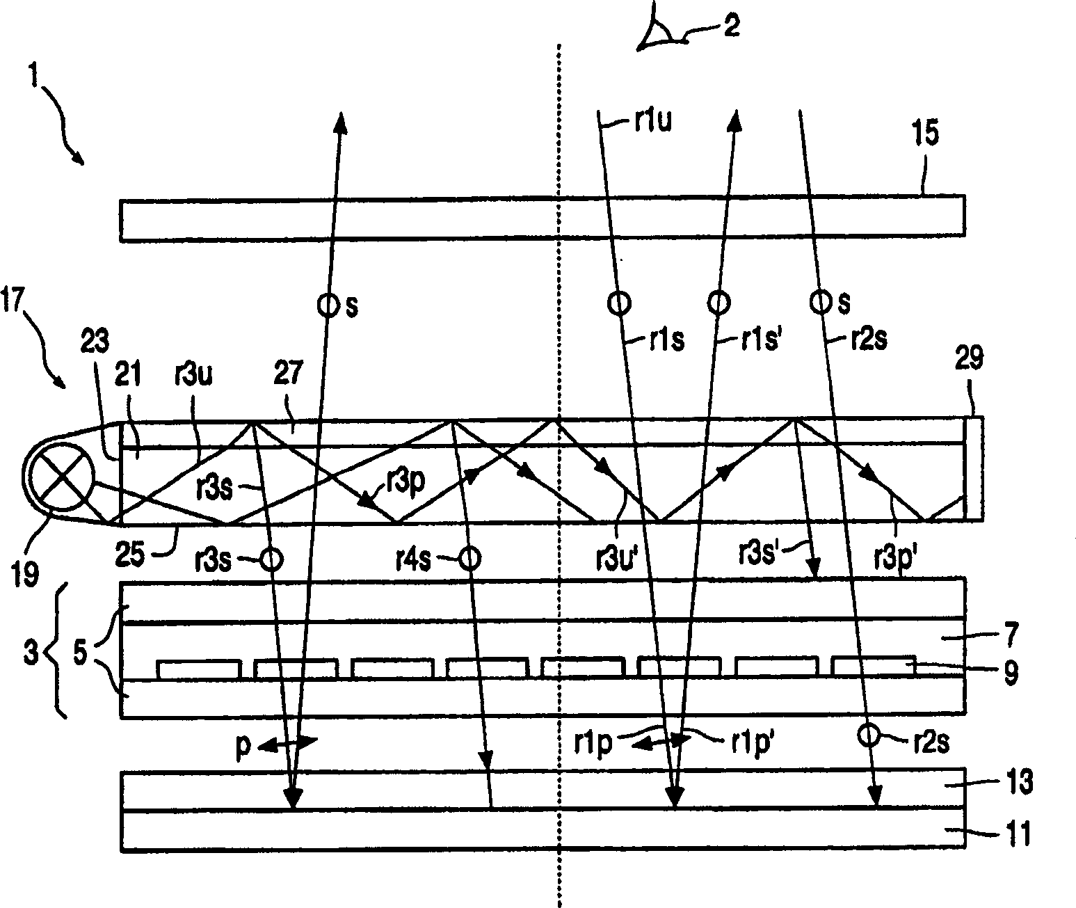
[0095] figure 1 A reflective display device 1 is schematically shown, a display cell (cell) 3 having transparent substrates 5 between which a liquid crystal layer 7 is arranged. The structure of the unit 3 comprises several individually addressable pixels 9 . A reflector 11 is arranged on the opposite side from the viewing side (indicated by viewer 2) and is provided with an absorbing linear polarizer 13 to absorb light of a first polarization and transmit light of a second polarization. Between the viewer 2 and the display unit 3 there is a second absorbing linear polarizer 15 crossed with the polarizer 13 for transmitting light of the first polarization and absorbing light of the second polarization. The display device 1 also comprises a frontlight 17 which is arranged between the polarizer 15 and the display unit 3 . The front light 17 is provided on the display side of the polarizer 15, rather than on the viewing side as is conventional, to reduce reflections off the fro...


PUM


Abstract

A polarized light-emitting waveguide for use in an edge-lit lighting arrangement /77) has polarization-selective outcoupling means including at least a volume hologram (87) for selectively diffracting waveguided light towards the exit surface of the waveguide with high contrast and efficiency. The light emitted by the waveguide is selectively emitted to one side thereof , highly polarized, highly collimated and may be homogeneously distributed across the exit surface. Also, light emission may be normal or near-normal to the exit surface. If combined with light recycling means (89) the contrast, brightness and/or efficiency of the edge-lit illumination arrangement may be further increased.

Description

technical field [0001] The present invention relates to a waveguide having an entrance side for coupling light into the waveguide and an exit side for light out of the waveguide. The invention also relates to an edge-emitting lighting device comprising such a waveguide and a display comprising such a waveguide or edge-emitting lighting device. Background technique [0002] Such waveguides of the type mentioned in the opening paragraph are suitable for providing light from a light source arranged near the entrance side of the waveguide to such surfaces as display surfaces, in particular to liquid crystal displays (LCDs) such as arranged near the entrance surface of the waveguide. ) The display surface of this non-emissive display device. Generally, the exit surface extends parallel to the direction of the waveguide, and its area is much larger than the incident side. The light source is arranged on one side of the waveguide, thereby obtaining a compact, especially very thin...

Claims


Application Information

Patent Timeline
IPC IPC(8): G02F1/13357F21V7/04F21V8/00F21Y103/00G03H1/00
CPCG02B6/0056G03H1/0248G03H1/0408G03H2222/31G02F1/1335
Inventor H·J·B·贾格特C·巴斯蒂安森H·J·科内里斯森D·J·布罗尔
Owner KONINKLIJKE PHILIPS ELECTRONICS NV
Why Eureka
Try Eureka