
Forehead weared cold light source camera microscope or amplifier

A magnifying glass, cold light source technology, applied in magnifying glass, optics, optical components, etc., can solve the problems of small application range, limited observation, and the structure cannot be adjusted according to needs, and achieves the effect of increasing convenience, reducing weight, and facilitating focusing.

Inactive Publication Date: 2005-01-05
上海神猎光机电科技有限公司
View PDF0 Cites 17 Cited by
  • Summary
  • Abstract
  • Description
  • Claims
  • Application Information

AI Technical Summary

Problems solved by technology

However, although these two head-mounted magnifiers do not need to be hand-held for observation, they cannot be adjusted as needed due to their simple structure, so the observation is limited and the application range is small.

Method used


Image

  • Forehead weared cold light source camera microscope or amplifier
  • Forehead weared cold light source camera microscope or amplifier
  • Forehead weared cold light source camera microscope or amplifier

Examples


Embodiment 1

[0032] Such as Figure 6 As shown, the forehead-mounted cold light source camera microscope or magnifying glass used for microsurgery.

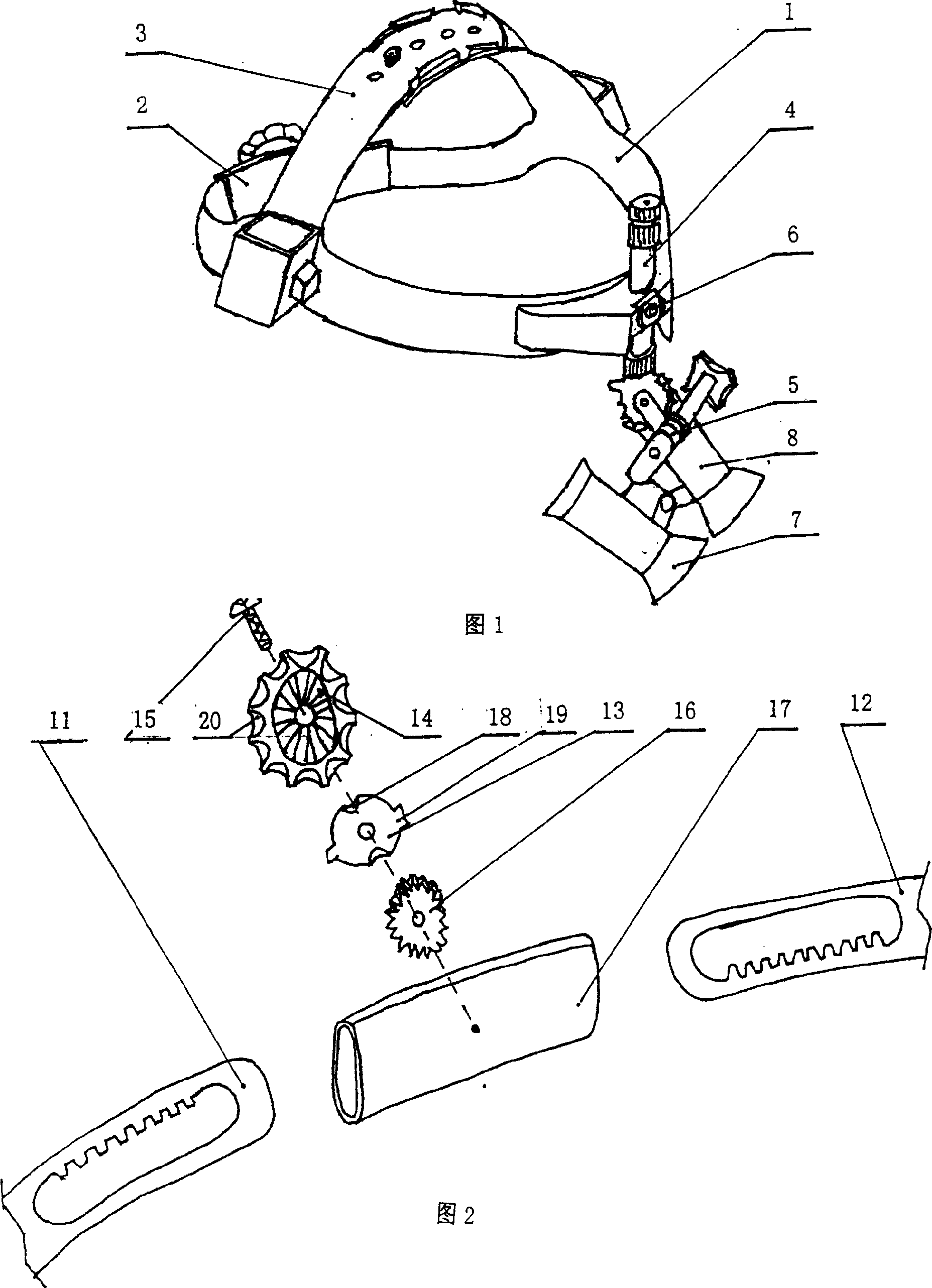
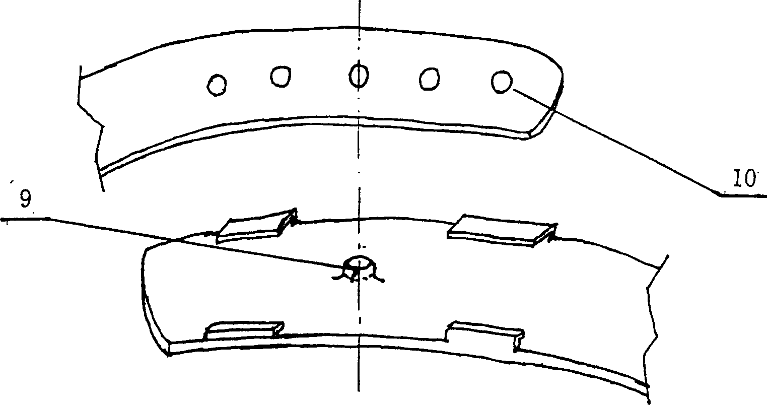
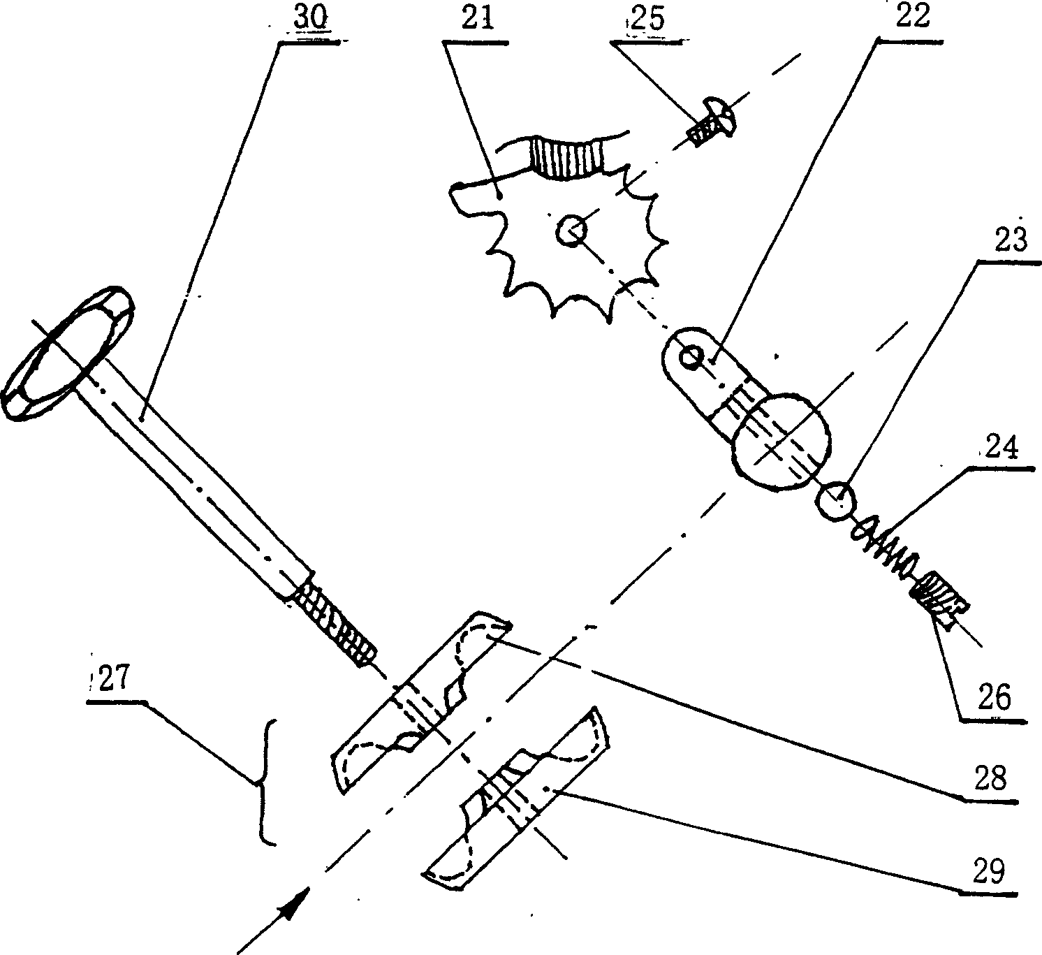
[0033] This embodiment includes: forehead-mounted helmet 1, helmet circumference adjustment mechanism 2, helmet embedded amount adjustment mechanism 3, microscope vertical displacement adjustment mechanism 4, microscope angle adjustment mechanism 5, forehead-mounted camera or system 6, forehead-mounted lighting System 7 and binocular microscope or magnifying glass 8 with adjustable interpupillary distance.

[0034] Microsurgery operations are generally performed and completed by a single doctor. During the operation, because the surgical site is very small, the eyesight of the human eye is easily fatigued under the condition of observing subtle objects for a long time. The general surgical magnifying glass is very inconvenient in operating focus and moving observation, which brings extra difficulty to the operation and increases the work in...

Embodiment 2

[0036] As shown in Figure 7, the forehead-mounted cold light source magnifying glass used for ENT examination.

[0037] This embodiment includes: a forehead-mounted helmet 1, a helmet circumference adjustment mechanism 2, a helmet embedded amount adjustment mechanism 3, a microscope vertical displacement adjustment mechanism 4, a microscope angle adjustment mechanism 5, a forehead-mounted lighting system 7 and an adjustable interpupillary distance. Binocular (or monocular) microscope or magnifying glass8.

[0038] When doing ENT examinations, doctors generally have to hold appropriate auxiliary tools. The current practice is to hold an inspection aid in one hand and a lighting device in the other, or wear the lighting device on the forehead separately. The disadvantage is that the equipment is scattered, and it is often impossible to complete the inspection or use all the tools at one time. The present invention uses the forehead-mounted light source magnifying glass 8 that ...


PUM


Abstract

The invention is a forehead cold light source shooting microscope or magnifier. It belongs to optical instrument field. The invention includes forehead armet, armet perimeter adjusting mechanism, armet embedding degree adjusting mechanism, microscope vertical shift adjusting mechanism, microscope angle adjusting mechanism, forehead illuminating mechanism, and monocular / binocular microscope or amplifier with adjustable pupilla distance. The forehead armet and the armet embedding degree adjusting mechanism are integral, the armet perimeter adjusting mechanism and the forehead armet are connected, the microscope vertical shift adjusting mechanism base is riveted with the forehead armet, the microscope vertical shift adjusting mechanism is connected with the microscope angle adjusting mechanism, the forehead illuminating system light source is embedded in the head of the monocular / binocular microscope or amplifier. The light source uses new source brightening diode cold light source, electricity saving, and the effect is better; the amplifier position can be adjusted in left, right, up and down.

Description

technical field [0001] The invention relates to an imaging microscope or magnifying glass, in particular to a forehead-mounted cold light source imaging microscope or magnifying glass. Used in the field of optical instruments. Background technique [0002] The commonly used low-magnification microscope or magnifying glass is fixed on the operating table, and then the object to be observed is placed in front of the objective lens, and the focal length is adjusted to achieve the purpose of observation. Its disadvantage is that it is difficult to observe objects that are large or inconvenient to move; to observe different parts of the object, the object needs to be moved and refocused, which affects the real-time performance of the observation and complicates the operation. Another kind of portable low-power microscope or magnifying glass can be directly placed in front of the eyes with both hands, which is convenient to move and focus, and makes up for the shortcomings of the...

Claims


Application Information

Patent Timeline
Patent Type & Authority Applications(China)
IPC IPC(8): A61B90/30G02B25/00
Inventor 胡天培高忠华
Owner 上海神猎光机电科技有限公司
Learn More