Machine oil pump of I.C. engine

A technology for oil pumps and internal combustion engines, applied to machines/engines, liquid fuel engines, pumps, etc., can solve problems such as oil leakage through mounting bolt holes, and achieve the effect of preventing oil leakage

Active Publication Date: 2005-01-12
盐城市大丰区生产力促进中心
View PDF1 Cites 14 Cited by
  • Summary
  • Abstract
  • Description
  • Claims
  • Application Information

AI Technical Summary

Problems solved by technology

However, in the actual use process, we found that there are still a few pumps with oil leakage in the mounting bolt holes

Method used


Image

  • Machine oil pump of I.C. engine

Examples


Embodiment Construction

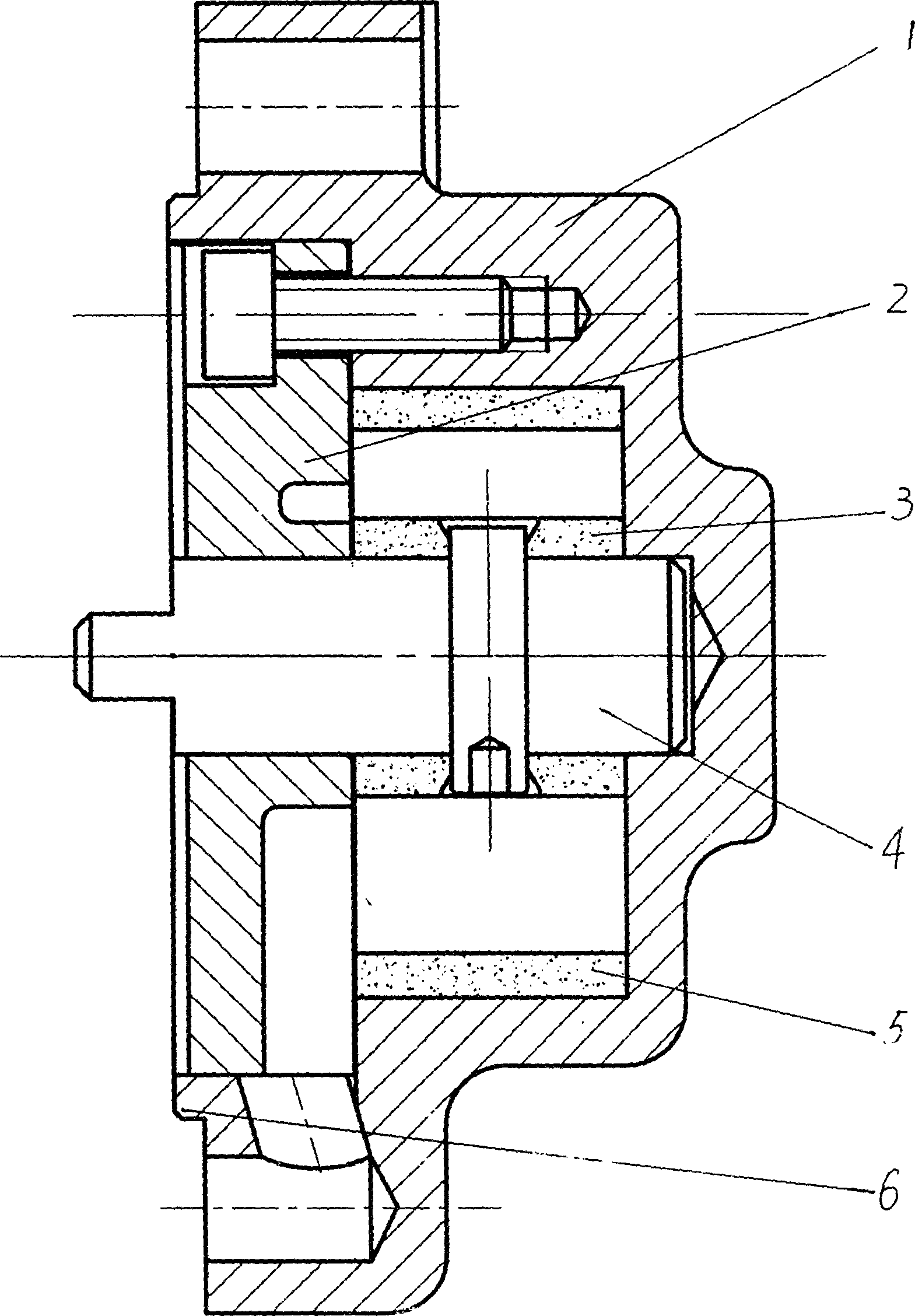
[0008] As shown in the figure, an internal combustion engine oil pump is composed of a pump casing (1), an inner rotor (3), an outer rotor (5), a shaft (4) and a flow plate (2). The inner and outer rotors (3, 5) The tooth profile is cycloid, the inner rotor (3) is located in the outer rotor (5), and is fixed on the shaft (4), there is a certain eccentricity between the inner and outer rotors (3, 5), and it is installed in the pump casing Inside (1), the pump casing (1) is in the shape of a concave disc, and there is a positioning boss (6) at the opening end of the pump casing (1), and the distribution plate (2) is embedded and fixed at the opening of the pump casing (1) , the surface of the distribution plate (2) is slightly lower than the surface of the boss (6), and one end of the shaft (4) is sleeved in the central hole of the distribution plate (2).


PUM


Abstract

The present invention relates to one kind of engine oil pump for internal combustion engine and is the improvement of inner meshed cycoidal gear pump of the present inventor for further eliminating oil leakage problem. The present invention consists of pump casing, inner rotor, outer rotor, shaft and flow distributing plate. The inner rotor is located inside the outer toro, fixed on the shaft and installed inside the casing; the inwards concave disc pump casing has one position boss in the opening for the flow distributing plate to be embedded; and the shaft has noe end set inside the central hole in the flow distributing plate. The present invention has positioning boss for installing the engine oil pump and diesel engine in the pump casing, rather than the flow distributing plate, and this makes it possible for oil leaking from the fitting seam between the flow distributing plate and the pump casing to flow fluently into the diesel engine to avoid oil leakage.

Description

Technical field [0001] The invention relates to an internal combustion engine oil pump, in particular to an internal combustion engine oil pump used in a lubricating system of a single-cylinder diesel engine. Background technique [0002] The patent No. ZL00216717.4 applied by me is an internal meshing cycloidal gear pump, which improves the split and superimposed structure of the original oil pump into an overall inclusive structure. In this structure, the surface of the valve plate is slightly higher than the end surface of the pump casing, just forming a positioning boss for oil pump installation. This internal meshing cycloidal gear pump solves the serious oil leakage problem of the original oil pump, and the output oil pressure can also be adjusted at the same time. However, in the actual use process, we found that there are still a few pumps with oil leakage in the mounting bolt holes. Contents of the invention [0003] The purpose of the present invention is to pr...

Claims


Application Information

Patent Timeline
Patent Type & Authority Applications(China)
IPC IPC(8): F01M1/02F04C2/10F16N13/20
Inventor 陈杰余
Owner 盐城市大丰区生产力促进中心
Why Eureka
Try Eureka