
Center line automatic locating method of virtual endoscope system

A virtual endoscope and automatic positioning technology, which is applied in the field of medical image processing and application, can solve the problems of many post-interventions, the center line cannot be completely guaranteed to be in the center position, and the operation is cumbersome, and achieves a good reference point and a good camera position. Controlled, adaptive effects

Inactive Publication Date: 2005-01-26
FUDAN UNIV
View PDF0 Cites 6 Cited by
  • Summary
  • Abstract
  • Description
  • Claims
  • Application Information

AI Technical Summary

Problems solved by technology

The viewpoint selection of the virtual endoscope in the prior art is generally a manually designated position (J.C.T Chen, M.L.Levy, A.PAmar, et al.Virtual endoscopic environments in modem neurosurgicalpractice.Neurosurg Focus, 1999; 6(4):Article 11) , it uses three planes to display the position of the current viewpoint in the three directions of space, adjusting the position of the viewpoint in the three directions determines the movement of the viewpoint. The disadvantage of this method is that the operation is cumbersome, and dragging a Observation from the point of view requires a certain concept of spatial anatomical position, so it limits its clinical application
Some researchers have explored automatic centerline finding methods (A.Vilanova, E.Groller, A.Konig. Cylindrical Approximation of Tubular Organs for Virtual Endoscopy by. Computer Graphics and Imaging 2000 Conference Proceedings, pp 283-289 and RD Swift, AP Kiraly, AJ Sherbondy, et al.Automatic axis generation for virtual bronchoscopic assessment of major airway obstructions.Computerized Medical Imaging and Graphics, 2002; 26(2):103-118), where columnar The main disadvantages of this method are as follows: 1. For some organs with complex structures, such as the colon, when distortions or pathological deformities occur, or even in normal bends, the centerline obtained cannot It is fully guaranteed that it is located in the center; 2. The degree of automation is not enough, and there are more interventions in the later stage

Method used


Image

  • Center line automatic locating method of virtual endoscope system
  • Center line automatic locating method of virtual endoscope system
  • Center line automatic locating method of virtual endoscope system

Examples


Embodiment 1

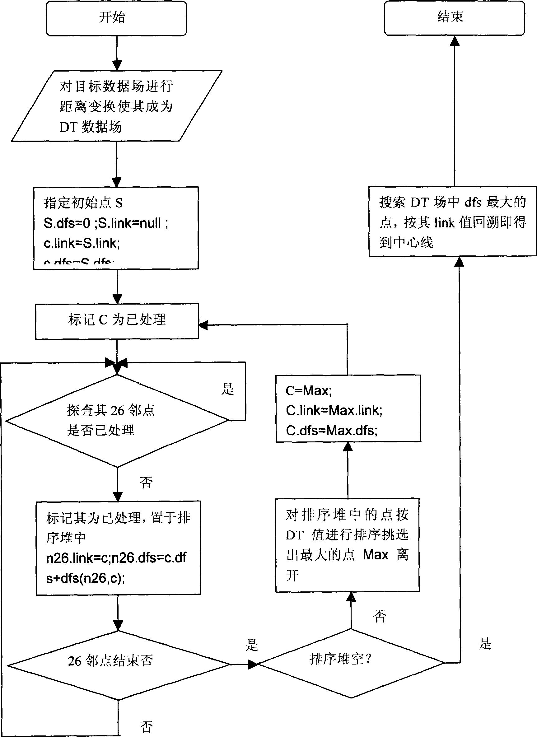
[0024] combine figure 1 , taking the continuous tomographic image obtained after CT scanning the colon as an example, the specific steps are as follows:

[0025] 1. The distance scale transformation is performed on the three-dimensional data field formed by the continuous CT tomographic images to form the distance data field (DT field) of the target object.

[0026] 2. The user selects the initial point.

[0027] 3. After initialization, the cyclic tree building process starts. The selection of nodes is determined according to the DT value of each node. Until the sorting heap is empty, each node is assigned a connection attribute and a distance attribute to the initial point.

[0028] 4. Search for the node with the largest distance to the initial point among the nodes, and backtrack to obtain the centerline of the colon.

[0029] 5. You can choose a new target point and repeat the process of 2, 3, and 4 as needed to solve the problem of interruption of the colon caused by p...


PUM


Abstract

A method of automatic imaging viewpoint positioning for intra-organ browsing in virtual endoscope system, belonging to the field of medical image processing and application. The invention firstly converts the data field (called by original data field in the following) derived from CT, MRI and other tomography images to a distance data field expressed by distance scale via distance transformation, and after the original point positioning, establishes a tree structure for the original data field by using maximum-cost spanning tree algorithm, obtains its longest branch, and accomplishes the generation of the center line of the virtual endoscope. The invention realizes automatic search of the center line of the virtual endoscope, avoids the operational trivialism and imprecision resulted from manual position assignment, acts accurately in positioning, and needs not to be amended.

Description

technical field [0001] The invention belongs to the field of medical image processing and application. The invention relates to a centerline automatic positioning method for browsing paths in a virtual endoscope system, so that the imaging viewpoint is automatically located at the center of a target organ. Background technique [0002] Virtual endoscope is based on the human body data field provided by medical imaging data (such as: CT, MRI, etc.), using computer technology to virtually observe multiple organs inside the human body, especially the internal surface of hollow organs, because it is similar to optical fiber Endoscopy, hence the name virtual endoscopy. It has some advantages that fiber optic endoscopes cannot replace, such as: suitable for the weak, infants, and those with severe stenosis of hollow organs. In addition, it has the characteristics of safety and non-invasiveness. welcome. [0003] The best view point of the hollow organ virtual endoscope is gener...

Claims


Application Information

Patent Timeline
IPC IPC(8): A61B1/00G06F17/00G06T1/00
Inventor 宋志坚姚德民李文生王满宁谢震中杜文健
Owner FUDAN UNIV
Learn More