Pneumatic flexible torsion joint

A flexible and articulated technology, applied in manipulators, program-controlled manipulators, manufacturing tools, etc., can solve the problems of high price, large volume, complex structure, etc., and achieve the effect of low cost, easy operation, simple and reasonable structure

Inactive Publication Date: 2005-01-26
ZHEJIANG UNIV OF TECH
View PDF0 Cites 8 Cited by
  • Summary
  • Abstract
  • Description
  • Claims
  • Application Information

AI Technical Summary

Problems solved by technology

However, they tend to b...

Method used


Image

  • Pneumatic flexible torsion joint
  • Pneumatic flexible torsion joint

Examples


Embodiment Construction

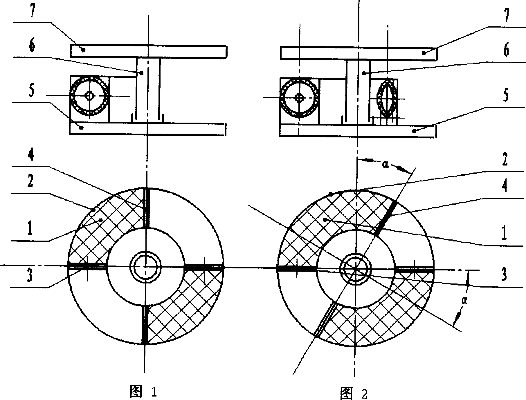
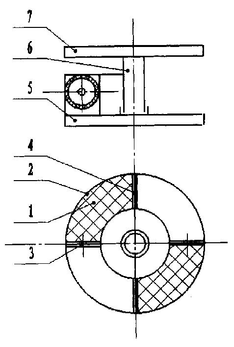
[0011] Accompanying drawing 1 and accompanying drawing 2 are an example of the present invention. As shown in accompanying drawing 1, the embodiment of the present invention is: a pneumatic flexible torsion joint, which is characterized by a pneumatic flexible cylinder 1, a metal sheet 2, end caps 3, 4, a fixed disc 5, a central shaft 6 and a circular turntable 7 The left and right ends of the pneumatic flexible cylinder 1 are respectively connected with the end covers 3 and 4, and the upper part of the pneumatic flexible cylinder 1 is provided with a metal sheet 2, and the metal sheet 2 is respectively connected with the end covers 3 and 4 at the left and right ends. 3. There is a through hole to communicate with the outside atmosphere. The end of the pneumatic flexible cylinder 1 connected to the end cover 4 is closed. Two pneumatic flexible cylinders 1 of the same size are arranged on the fixed plate 5 in axisymmetric left and right. The fixed plate 5 is equipped with a midd...


PUM


Abstract

The invention is a pneumatic soft torsion joint. The character is: it is made up of pneumatic soft cylinder, metal plate, and end cover, fixing plate, core and round turntable. Two pneumatic soft cylinders with the same size are arranged on the fixing plate symmetrically, the round turntable can rotate freely around the core relatively to the fixed plate. When inputting compressed air into the two cylinders, the round turntable will rotates for a certain angle by the pushing force of the pneumatic soft cylinder, forms the torsion movement process of robot. The structure is reasonable; the cost is low, reliable, and quick.

Description

technical field [0001] The invention belongs to a torsion joint, in particular to a pneumatic flexible torsion joint, which is suitable for the occasion of designing and manufacturing a manipulator. Background technique [0002] All driving parts of contemporary electric robots or hydraulically controlled robots are reciprocating or rotating. When they are used to build the joints of robots, it is usually necessary to have a set of mechanical devices to convert reciprocating or rotating motion into other motion modes required. Robotic joints designed in this way may have high precision and high output power. However, they tend to be bulky, complex and expensive. And flexibility is far behind the joints of the human body. [0003] Because of the above disadvantages of contemporary robot actuation components, the development of dexterous robot actuation components has become a common interest among robot makers, and robotics engineers are seeking new types of actuation comp...

Claims


Application Information

Patent Timeline
IPC IPC(8): B25J9/08
Inventor 张立彬杨庆华沈建冰阮健
Owner ZHEJIANG UNIV OF TECH
Why Eureka
Try Eureka