Electronic thermorelay

A thermal relay, electronic technology, used in electrical components, emergency protection circuit devices, protection against overcurrent, etc., can solve the problems of slow heating action of thermal components, difficult protection action, and prolonged limit switch time. , to achieve the effect of overcoming poor movement consistency and improving product quality

Inactive Publication Date: 2005-01-26
YUEQING HONGSHENG ELECTRONICS APPLIANCES
View PDF3 Cites 4 Cited by
  • Summary
  • Abstract
  • Description
  • Claims
  • Application Information

AI Technical Summary

Problems solved by technology

But it has the following disadvantages and deficiencies: (1) Three sets of thermal elements are required to drive a complex mechanical mechanism, which makes it difficult to ensure the consistency of action; (2) The thermal element is installed on the bracket in the air, and the actuator needs to be pushed after being heated and bent. Then push the limit switch, because the mechanism resistance and the error of the mechanical mechanism are very large, it is difficult to complete the precise protection action; (3) due to the slow heating action of the thermal element, when the mechanism and the limit switch are close to the zero boundary state, the limit switch The contacts are in a non-connected state, and it is easy to damage the electrical equipment and the motor; (4) Although there is a phase-break protection function, the effect is very poor. It needs to act for a long time, and only the other two-phase thermal elements are working, so the time to push the limit switch is greatly increased, it is impossible to achieve the purpose of protection in a timely manner, and it is easy to damage electrical equipment and motors

Method used


Image

  • Electronic thermorelay
  • Electronic thermorelay
  • Electronic thermorelay

Examples


Embodiment Construction

[0016] The present invention and its positive effects will be further described below in conjunction with the embodiments and accompanying drawings.

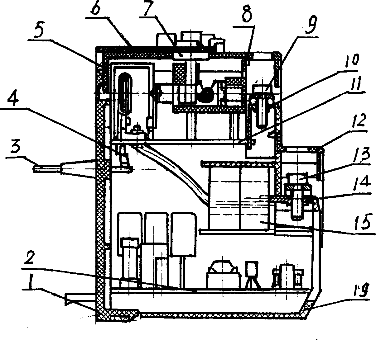
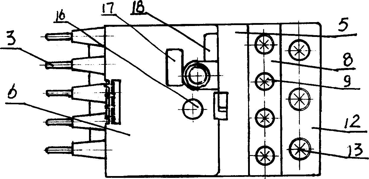
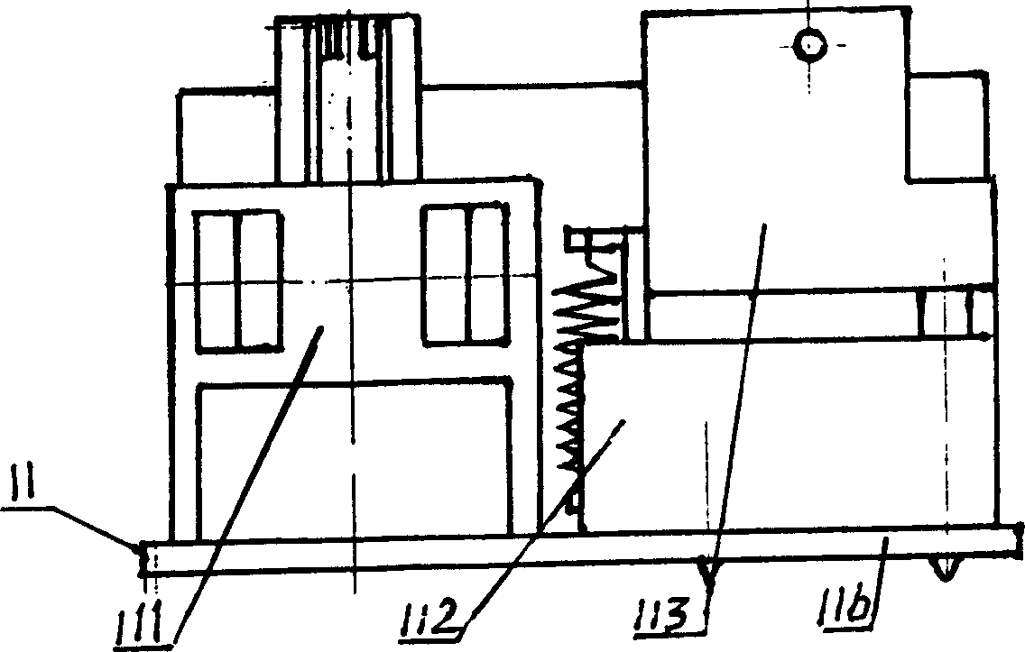
[0017] see Figure 1 to Figure 5 , an electronic thermal relay, which is mainly composed of a housing, a terminal block, a reset button 18, an indicator light 16 and a circuit device 2, the lower part of the housing is provided with the circuit device 2, and the upper part is provided with a measuring device 11, the measuring device 11 On the support plate 116, an electrical command electromagnetic control relay 112, a single-phase bimetallic heating element 115 and a Hall element H for detecting the running distance of the single-phase bimetallic heating element 115 are arranged, and the circuit device 2 includes a protection circuit 22 The protection circuit 22 is mainly composed of an integrated circuit IC, the Hall element H is connected to the integrated circuit IC, and the measurement signal of the Hall element H is operat...


PUM


Abstract

The invention is an electronic thermal relay, composed mainly of shell, terminal, reset button, indicator light and circuit device, where the circuit device is arranged in the lower part of the shell, a measurer is arranged in the upper part of the shell and provided with equipment instruction electromagnetic control relay, single-phase double-metal thermal component and Hall component to detect traveling distance of the single-phase double-metal thermal component, and the circuit device includes a protecting circuit, composed mainly of IC (integrated circuit), the Hall component is connected with the IC, the measured signal of the Hall component instructs the electromagnetic control relay to act through IC operation instruction equipment. Its switching-on and -off are clear and the current overload protection for the motor is effective and accurate.

Description

1. Technical field [0001] The invention relates to a relay, in particular to an electronic thermal relay. 2. Background technology [0002] Thermal relay is a kind of electrical appliance that relies on the heat generated when the current passes through the heating element, so that the bimetal sheet is heated and bent to push or command the action of the mechanism. It is mainly used for overload protection of the motor, protection of phase failure and current unbalanced operation, and other The control of the heating state of electrical equipment is mainly composed of three parts: the heating element, the control contact and the action system, and the reset mechanism. Existing thermal relays mainly use bimetal strips and resistance wires or strips to form thermal elements, and each phase of the three-phase power supply is in one group. When the motor is overloaded, the current increases, the resistance wire heats up, the bimetal sheet bends in a single direction, and the li...

Claims


Application Information

Patent Timeline
IPC IPC(8): H02H3/08H02H7/085H02H7/09
Inventor 潘建生潘少秋
Owner YUEQING HONGSHENG ELECTRONICS APPLIANCES
Why Eureka
Try Eureka