Separately controlled printed circuit board

A technology for printed circuit boards and control circuits, which is applied in the directions of printed circuit components, structural connections of printed circuits, instruments, etc., and can solve problems such as large area and breakage of flexible circuit boards.

Inactive Publication Date: 2005-01-26
AU OPTRONICS CORP
View PDF0 Cites 9 Cited by
  • Summary
  • Abstract
  • Description
  • Claims
  • Application Information

AI Technical Summary

Problems solved by technology

[0007] In addition, since the traditionally used source control printed circuit board 15 and gate control printed circuit board 12 have relatively large areas, the flexible circuit board 17 or TCP 14 must be bent before the source control printed circuit board 15 can be assembled. Lock

Method used


Image

  • Separately controlled printed circuit board
  • Separately controlled printed circuit board
  • Separately controlled printed circuit board

Examples


no. 1 example

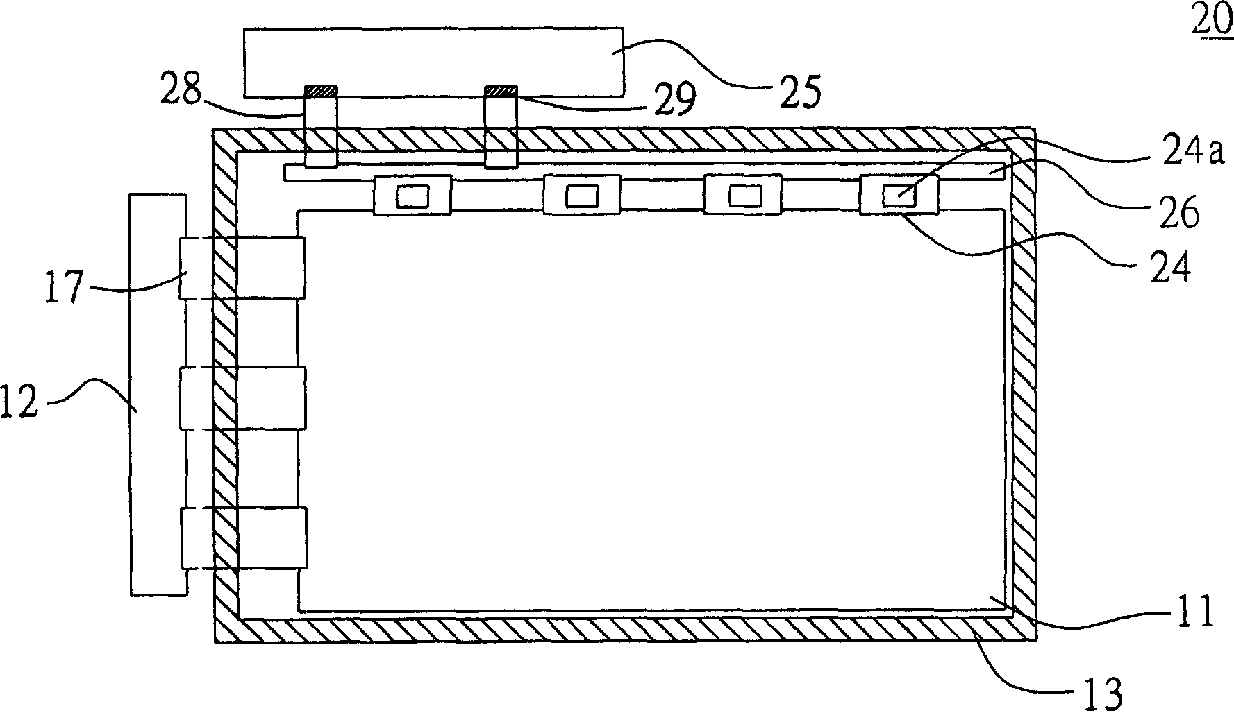
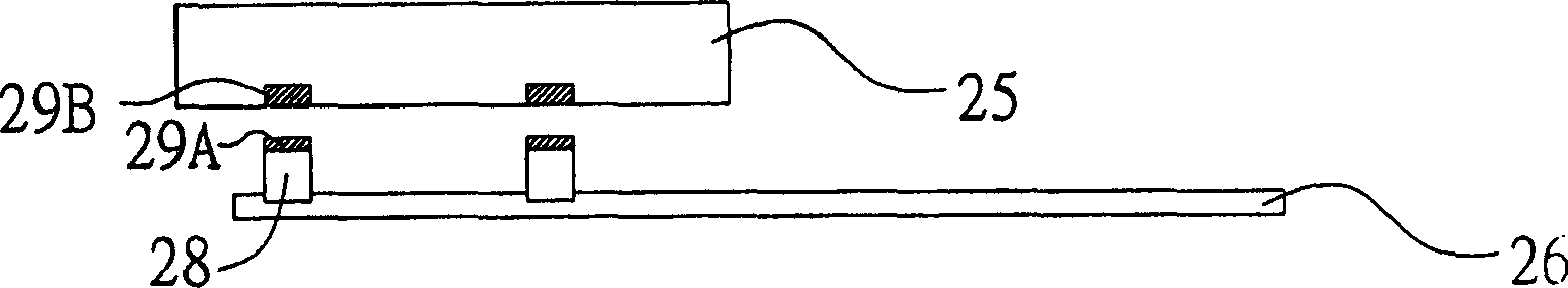
[0035] Please refer to Figure 2A , which is a partial schematic view of the display according to the first embodiment of the present invention. The liquid crystal display 20 includes a separate control printed circuit board composed of a main source circuit board 25 and an auxiliary source circuit board 26, a gate control printed circuit board 12 and a plurality of flexible circuits connected thereto board (FPC) 17 , a display panel 11 and a frame 13 . A control circuit is configured on the main source circuit board 25 for outputting control signals. The auxiliary source circuit board 26 is electrically connected to the main source circuit board 25 via a plurality of flexible circuit boards 28 . The auxiliary source circuit board 26 is electrically connected to the display panel 11 by at least one TCP 24 , and the circuit on the auxiliary circuit board 26 can transmit or amplify the control signal of the main circuit board 25 to the display panel 11 . Each TCP 24 is configu...

no. 2 example

[0041] The separated control printed circuit board of the present invention can also be applied to the grid control printed circuit board. The grid control printed circuit board is separated into a main grid circuit board and an auxiliary grid circuit board. Please refer to FIG. 3A , which is a partial schematic diagram of a display according to a second embodiment of the present invention. The liquid crystal display 30 includes a separate grid control printed circuit board and a source control printed circuit board composed of a main grid circuit board (Main Gate PCB) 32 and an auxiliary grid circuit board (Auxiliary Gate PCB) 33 (Source PCB) 15 and the TCP 14 connected thereto, a display panel 11 and an outer frame 13 .

[0042] The auxiliary grid circuit board 33 is electrically connected to the main grid circuit board 32 through a plurality of flexible circuit boards 38 , and the auxiliary grid circuit board 33 is also electrically connected to the display panel 11 throug...

no. 3 example

[0046] According to the third embodiment of the present invention, the separate control printed circuit board can also be applied to the source control printed circuit board and the gate control printed circuit board at the same time. Please refer to FIG. 4 , which is a partial schematic diagram of a display according to a third embodiment of the present invention. The liquid crystal display device 40 of the third embodiment of the present invention includes a separate source control printed circuit board composed of a main source circuit board 45 and an auxiliary source circuit board 46, and a main gate circuit board 42 and an auxiliary source circuit board 46. A separate grid control printed circuit board composed of an auxiliary grid circuit board 43, a flexible circuit board (FPC) 47 connected to the auxiliary grid circuit board 43, a TCP44 connected to the auxiliary source circuit board 46, a The display panel 11 and an outer frame 13 .

[0047] The main source circuit b...


PUM

PropertyMeasurementUnit
Widthaaaaaaaaaa

Abstract

The invention discloses a separate type control printed circuit board using for display plate, including the main circuit plate and the subsidiary circuit plate. The main circuit plate stations a control circuit for outputting control signal, and the subsidiary circuit utilizes flexible circuit plate, flexible drop-out plate line and linker to connect with main circuit plate. The subsidiary circuit utilizes TCP of tape coiling type or flexible circuit plate to connect with display plate, and the line on the subsidiary circuit plate can transport or magnify the control signal of main circuit plate to display plate. The invention only need changing the main circuit plateí»s design to achieve modularization, the assemble package is easy and can saving time, and it does not need designing differ implement to match differ circuit plate to bear the weight.

Description

technical field [0001] The present invention relates to a separate control printed circuit board, and in particular to a separate control printed circuit board applicable to a display panel. Background technique [0002] The control printed circuit board (Printed Circuit Board, PCB) is an indispensable basic component of all information electronic products. It acts as the main carrier when installing and plugging various electronic components. A kind of electronic components, by controlling the circuit design of the printed circuit board, the purpose of relay transmission is achieved, so that the functions of various components can be brought into play. [0003] The control printed circuit board can be electrically connected to other substrates or through flexible circuit boards (Flexible Printing Circuit board, FPC), tape carrier packages (Tape Carrier Package, TCP) or flexible cables (FFC). interface. Taking the liquid crystal display module as an example, the source con...

Claims


Application Information

Patent Timeline
IPC IPC(8): G09F9/30H05K1/14
Inventor 刘丞佑康清志
Owner AU OPTRONICS CORP
Why Eureka
Try Eureka