
Cable modem module and transmitter-receiver

A technology for modems and receivers, used in instruments, televisions, connections, etc., to solve problems such as reduced work performance and assembly efficiency, broken terminals, and deformation.

Inactive Publication Date: 2005-02-02
KK TOSHIBA
View PDF1 Cites 2 Cited by
  • Summary
  • Abstract
  • Description
  • Claims
  • Application Information

AI Technical Summary

Problems solved by technology

Due to this, work performance and assembly efficiency are reduced
[0010] Also, trying to fit the shield containing the RF connector and circuit board into an enclosure with little space can cause the terminals to break or deform when, for example, a set of terminals protruding from the circuit board and the RF connector are oriented in different directions

Method used


Image

  • Cable modem module and transmitter-receiver
  • Cable modem module and transmitter-receiver
  • Cable modem module and transmitter-receiver

Examples


Embodiment Construction

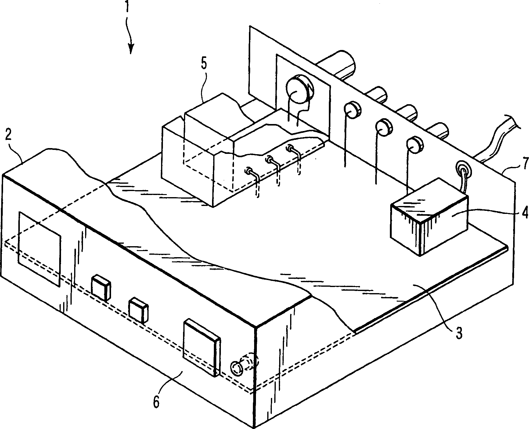
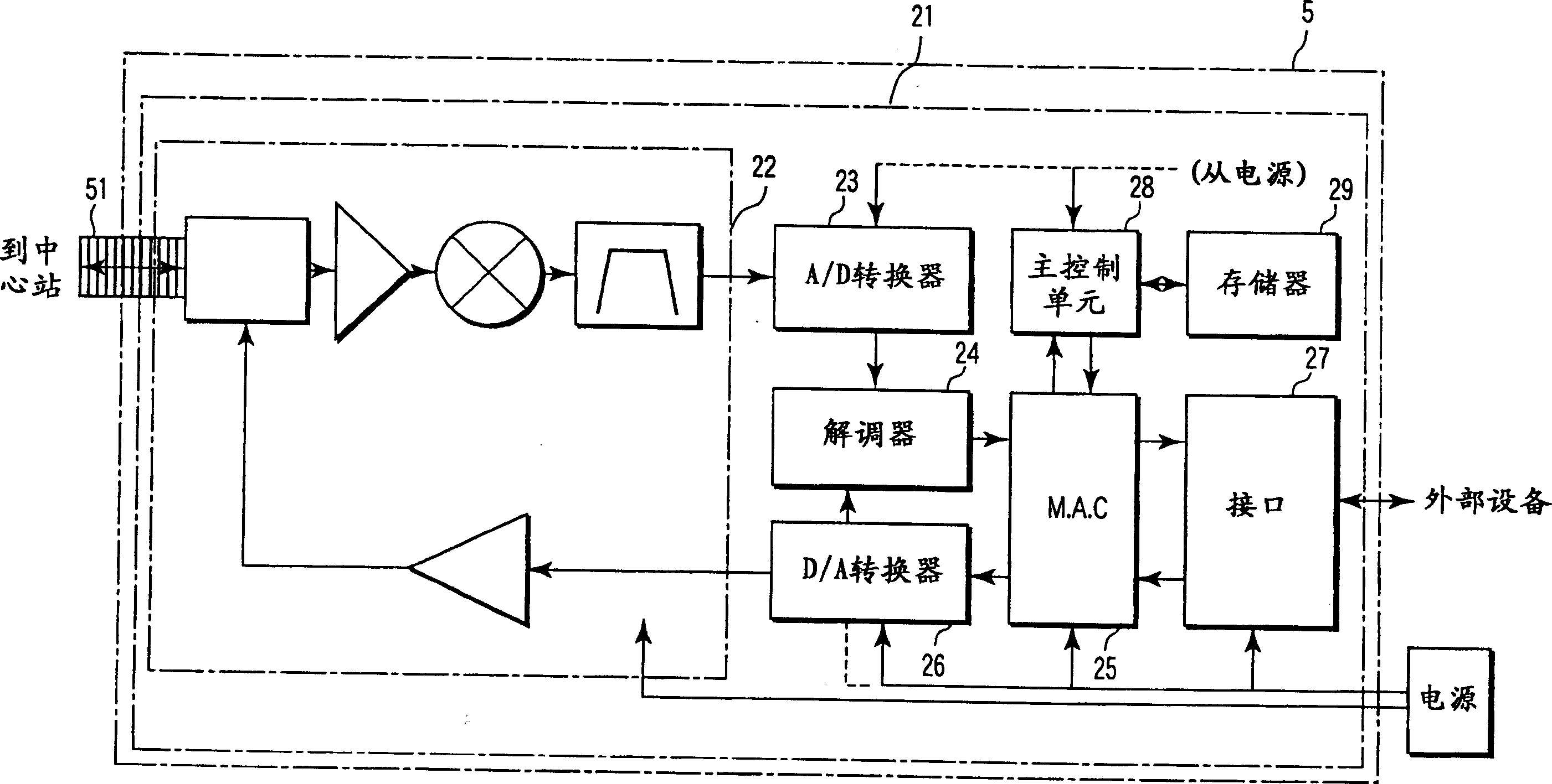
[0020] An embodiment of the present invention will be described in detail below with reference to the accompanying drawings. figure 1 Shown is cable television (CATV) terminal equipment generally indicated by 1 as a data communication terminal, which is connected to the CATV network and enables the user to receive video programs, music programs, or character data transmitted from a radio station and to be input by him or her. Information sent to program transmitters.

[0021] Video signals or character data are transmitted from the center station to each terminal (user) by a high-frequency reception signal (downlink signal) of the order of, say, 90 to 860 MHz. On the other hand, information can be transmitted from each terminal to the central station by means of high frequency transmission signals of the order of say 5 to 65 MHz.

[0022] Such as figure 1 As shown in , a CATV terminal device 1 includes a housing 2 , a main circuit board 3 , a power supply circuit board 4 , a...


PUM


Abstract

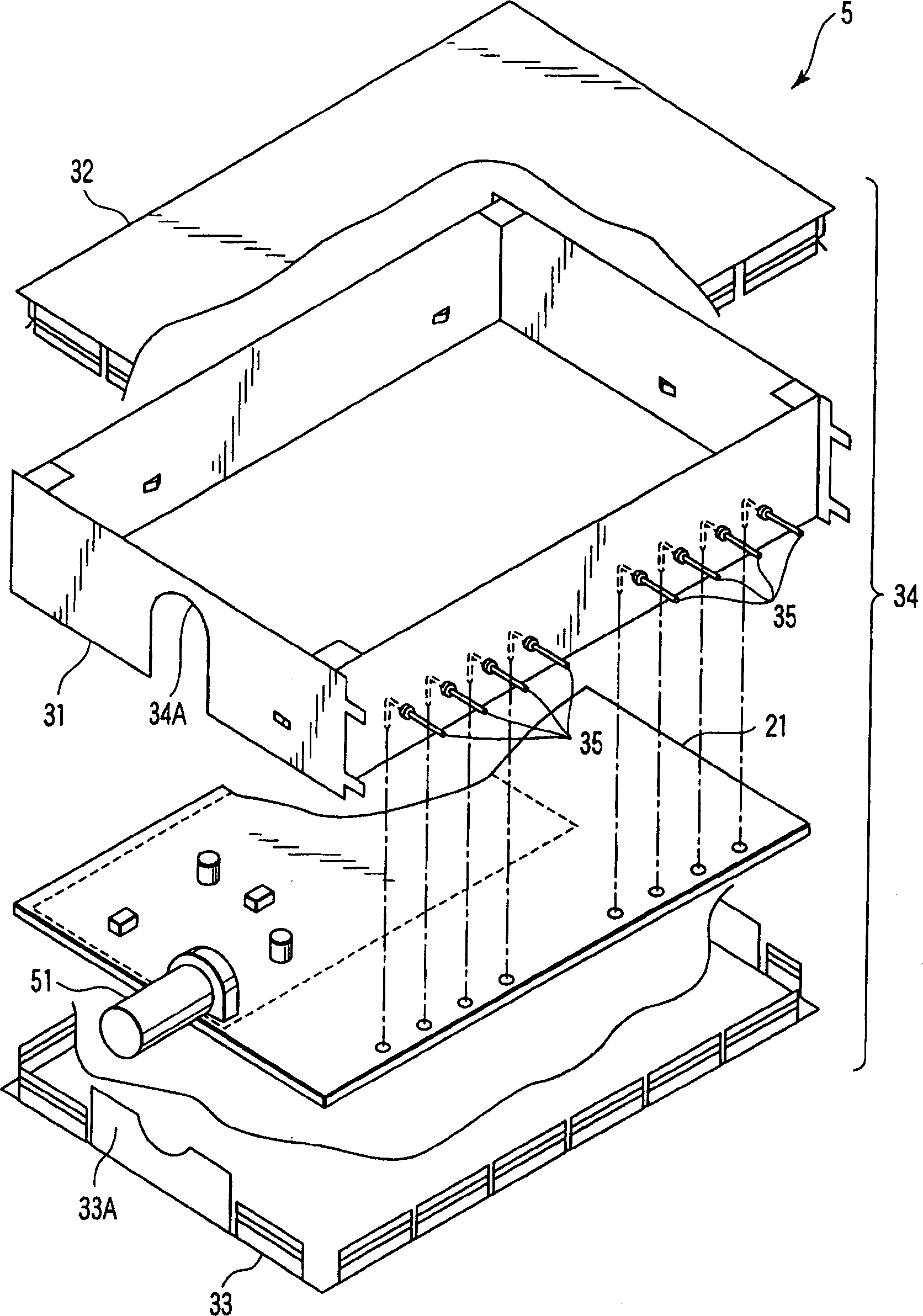
A cable modem module device comprising a coaxial connector to transmit and receive high-frequency signals, a circuit board to which the coaxial connector is attached to protrude from its periphery in a direction parallel to its surface, and a first shield case formed in its portion corresponding to the coaxial connector with a cutout portion to avoid the coaxial connector so as to allow the circuit board to be housed from a direction perpendicular to the surface of the circuit board.

Description

technical field [0001] The present invention relates to a cable modem module which enables reduction of harmful radiation from signal terminals mounted on a circuit board adapted to process signals input to or output from the circuit board via coaxial connectors, where harmful radiation may be superimposed on input signal or output signal. The invention also relates to a transmitter-receiver incorporating such a cable modem module. Background technique [0002] In a transmitter-receiver that receives a signal from the outside through a radio frequency (RF) cable (coaxial connector) or sends a signal processed by an internal circuit to the outside, the circuit board is placed in a protective case made of metal, etc., to protect the The shell has the function of preventing or reducing harmful electromagnetic radiation. This prevents harmful radiation from being superimposed on received signals to be processed by the circuit board or signals generated by the circuit board. ...

Claims


Application Information

Patent Timeline
Patent Type & Authority Applications(China)
IPC IPC(8): H05K9/00G12B17/02H01R12/00H04B3/02H04N5/38
CPCH04L12/2898H01R2103/00H01R24/50H05K9/006H04L12/2801
Inventor 安部修二工藤雄也矶田勉大泽昌巳藤原干根
Owner KK TOSHIBA
Learn More