Method for the manufacture of a piston

A manufacturing method, piston technology, applied in the direction of pistons, shock absorbers, transportation and packaging, etc., can solve the problems of small indentation, difficult adjustment of vibration damping force, etc., to reduce the indentation, diameter and/or thickness Increased effect

Inactive Publication Date: 2005-02-09
ZF FRIEDRICHSHAFEN AG
View PDF1 Cites 2 Cited by
  • Summary
  • Abstract
  • Description
  • Claims
  • Application Information

AI Technical Summary

Problems solved by technology

However, it turns out that the pressed-in support ring produces a small indentation effect when the spool is fastened to the piston, which may become more pronounced locally on the spool edge and thus create small leak points, These leak points especially have a negative effect on the increasingly difficult adjustment of the damping force on the piston valve

Method used


Image

  • Method for the manufacture of a piston
  • Method for the manufacture of a piston

Examples


Embodiment Construction

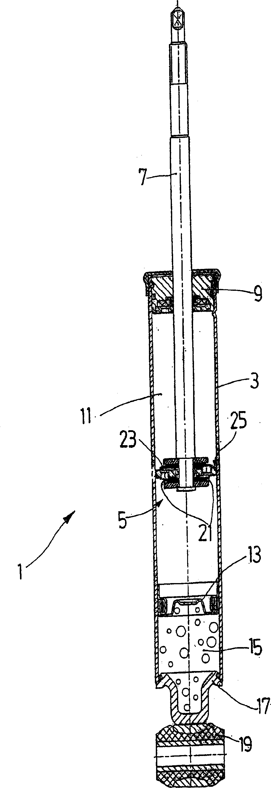
[0016] FIG. 1 shows an example of a piston-cylinder unit 1 in the form of a monotube shock absorber. In principle, the invention can also be used in other or piston-cylinder units.

[0017] A monotube shock absorber 1 essentially comprises a pressure tube 3 in which a piston 5 is mounted axially displaceable on a piston rod 7 . On the outlet side of the piston rod 7, a piston rod guide 9 closes a working chamber 11 filled with a damping medium, which is separated by a separating plug 13 from a gas chamber 15 which has a hole 19 at the end. Bottom plate 17.

[0018] When the piston rod is moved, damping medium flows through a damping valve 21 in the piston 5 , which is formed by a spool 23 . A piston ring 25 covering the outer circumference of the piston 5 prevents the flow of damping medium around the piston and takes over the task of guiding the piston in a friction-reduced manner.

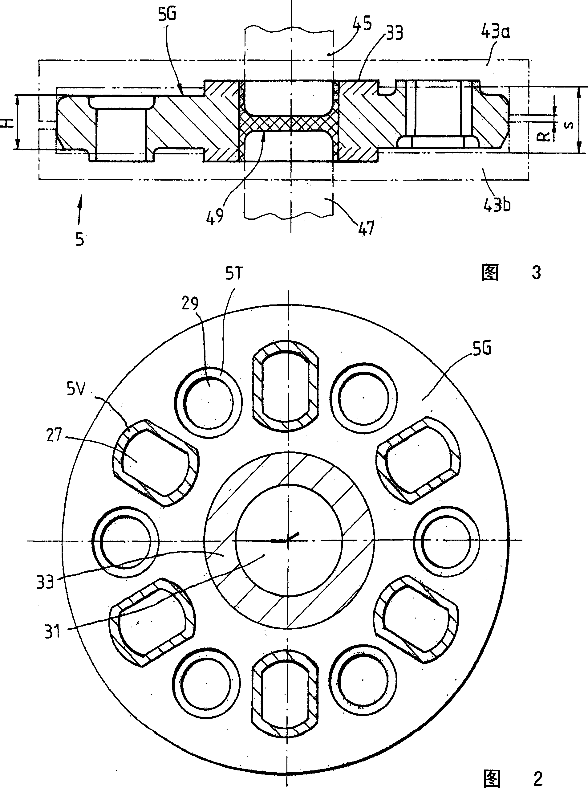
[0019] FIG. 2 shows a plan view of the piston 5 in the finished state. Projecting from th...


PUM


Abstract

Method for the manufacture of a piston, wherein the piston comprises a piston body with through-channels for fluid which are covered by valve disks on support bodies with valve support surfaces, wherein the piston body is disk-shaped and is constructed in one piece by means of press stamping and, starting from a base body of the piston, the support bodies which are raised on one side of the piston are formed as recesses on the axially opposite side of the piston, and the piston has at least one support for the valve disks which is likewise pressed out of the piston base body on both sides of the piston, wherein the support of the piston body is formed from the piston body in a die tool by material flow against the pressing movement of a forming tool.

Description

technical field [0001] The invention relates to a method of manufacturing a piston according to the preamble of claim 1 . Background technique [0002] DE19735249C1 discloses a stamped piston. A plurality of seat surfaces projecting on both sides as well as a central seat for the valve plug protrude from the piston base body. Both the support seat and the valve seat surface are alternately punched by the piston body. As can be seen from DE 197 35 249 C1 in the region of the narrow portion 37 in FIG. 3 , the non-deformable material volume partially limits the dimensions of the support in the circumferential direction as well as the outer diameter. In order to precisely adjust the damping force, the diameter of the bottom surface of the spool resting on the support must be as large as or preferably larger than the outer diameter of the fastening disc or the fastening nut on the top surface of the spool. Insufficient support of the spool on the bottom surface can lead to flu...

Claims


Application Information

Patent Timeline
Patent Type & Authority Applications(China)
IPC IPC(8): B21D53/84B21K1/18B23P15/10F16F9/32F16F9/34
CPCF16F9/3214B23P15/10F16F9/3405B21K1/18B23P2700/14Y10T29/49249
Inventor W·彼得F·格拉尔德A·哈桑
Owner ZF FRIEDRICHSHAFEN AG
Why Eureka
Try Eureka