Warp knitting machine

A technology of warp knitting machine and traction parts, which is applied in the field of warp knitting machines, can solve the problems of damage to traction parts, confusion, etc., and achieve the effect of saving space

Inactive Publication Date: 2005-02-09
KARL MAYER CHINA
View PDF1 Cites 3 Cited by
  • Summary
  • Abstract
  • Description
  • Claims
  • Application Information

AI Technical Summary

Problems solved by technology

Even when changing e.g. bar units with a different distribution of the yarn guides, the drawing elements can be disturbed and damaged

Method used


Image

  • Warp knitting machine
  • Warp knitting machine
  • Warp knitting machine

Examples


Embodiment Construction

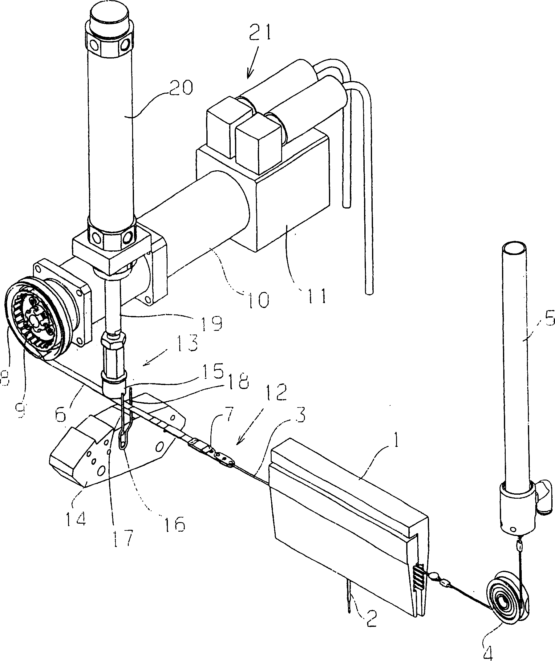
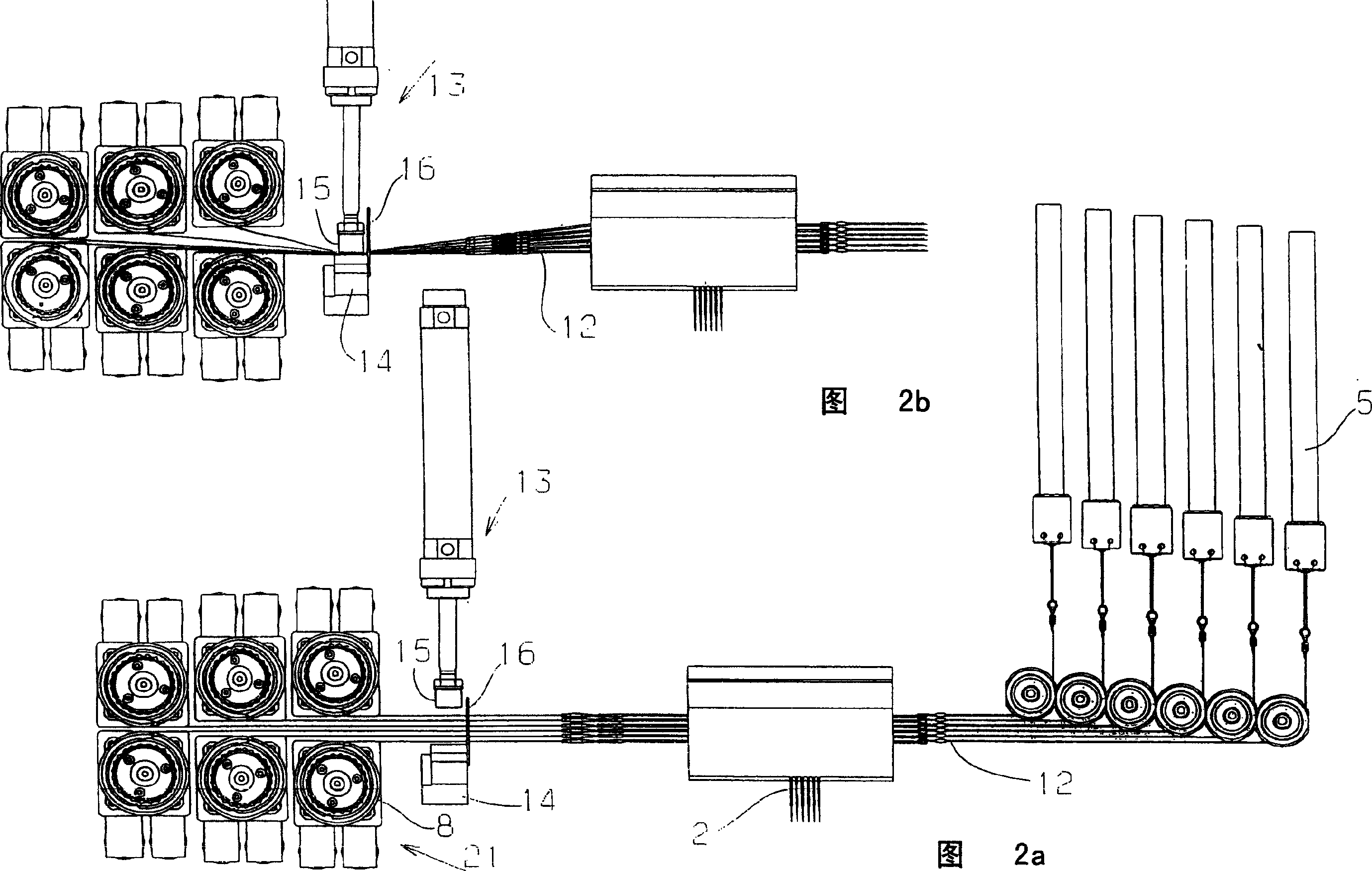
[0030] figure 1 A partial schematic view of a warp knitting machine with a drawing element 1 with a thread guide 2 is shown. There are generally a plurality of flower bars on a warp knitting machine. Each flower bar usually has more than one yarn guide 2 again. while in figure 1 The warp knitting machine partially shown in the center serves to simplify the description.

[0031] Yarn guide 2 is fixed on the wire rope 3. If the wire rope 3 moves back and forth, the yarn guide 2 also moves back and forth in the traversing direction. The traverse direction extends parallel to the longitudinal direction of the steel wire rope 3 .

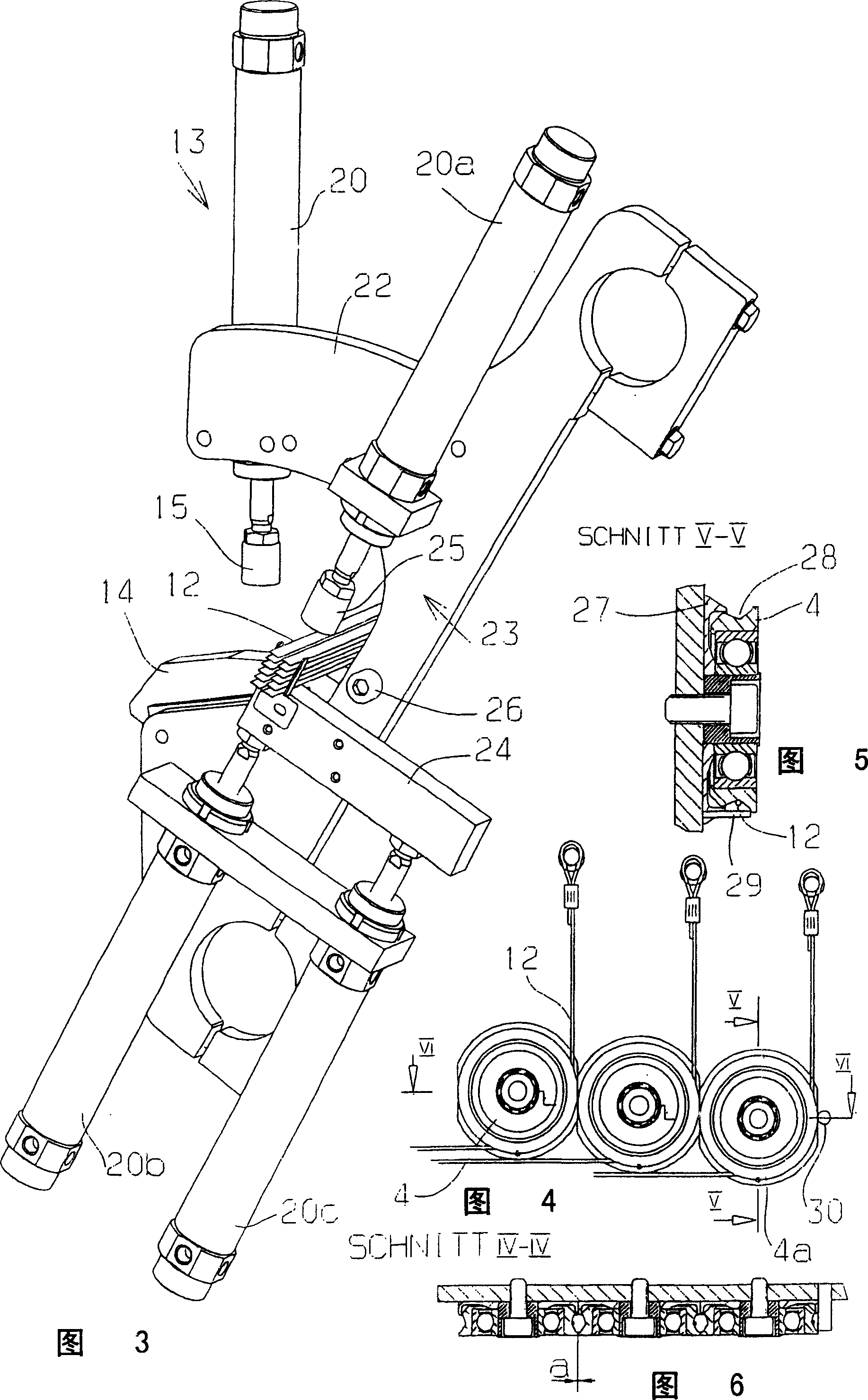
[0032] at one end ( figure 1 On the right side), the wire rope 3 moves to the tensioning device 5 through a guide roller 4 . The tensioning device 5 produces a tensioning force on the wire rope 3 which is independent of the stroke length. For this purpose, the tensioning device 5 is, for example, a compressed air cylinder.

[0033] At the other ...


PUM


Abstract

A warp loom has a pattern lay-up bar (1) with several thread guides (2) set in back and forth motion by a strap and cable link (12) to a drive unit (21). The strap section moves through a holding clamp-guide (13). - The assembly has groups of strap and cable links (12). Each strap is in surface contact with the next strap. The operation of each group is regulated by a single holding clamp-guide (13). During operation the clamp is operated if the supply of compressed air to the loom should fail.

Description

technical field [0001] The invention relates to a warp knitting machine (Kettenwirkmaschine), which is provided with at least one flower bar, which is provided with a plurality of yarn guides which can be moved back and forth in the traverse direction by a driving device, wherein, between the yarn guide and A traction piece is arranged between the driving devices. Background technique [0002] Such a warp knitting machine is disclosed in DE 101 37 601 . Here, the yarn guide is suspended from a steel wire or a steel cable which is connected at both ends to the tensioning element by a tensioning band, so that the same force is applied to both ends of the steel cable. Thus, the drive motor around which the tensioning belt is wound on its drive wheel can only apply the force required for the movement of the yarn guide. However, drive motors cannot apply the force required to tension springs or other tensioning devices. Here, the tensioning device is an air cylinder, and the t...

Claims


Application Information

Patent Timeline
IPC IPC(8): D04B23/00D04B27/24
CPCD04B27/24D04B23/00
Inventor K·米斯塔J·菲舍尔A·布罗施
Owner KARL MAYER CHINA
Why Eureka
Try Eureka