Cathode ray tube having an improved shadow mask

A cathode ray tube and shadow mask technology, applied in the direction of cathode ray tube/electron beam tube, cathode ray/electron beam tube casing/container, discharge tube, etc. Weak strength, affecting the overall quality of the shadow mask, etc.

Inactive Publication Date: 2005-02-09
LG PHILIPS DISPLAY KOREA CO LTD
View PDF0 Cites 0 Cited by
  • Summary
  • Abstract
  • Description
  • Claims
  • Application Information

AI Technical Summary

Problems solved by technology

[0032] In short, the shadow mask of the prior art caused the problem of weak strength in the minor axis direction, which ultimately affected the overall quality of the shadow mask and degraded the image quality of the cathode ray tube

Method used


Image

  • Cathode ray tube having an improved shadow mask
  • Cathode ray tube having an improved shadow mask
  • Cathode ray tube having an improved shadow mask

Examples


Embodiment Construction

[0056] The following detailed description will describe a cathode ray tube according to a preferred embodiment of the present invention with reference to the accompanying drawings.

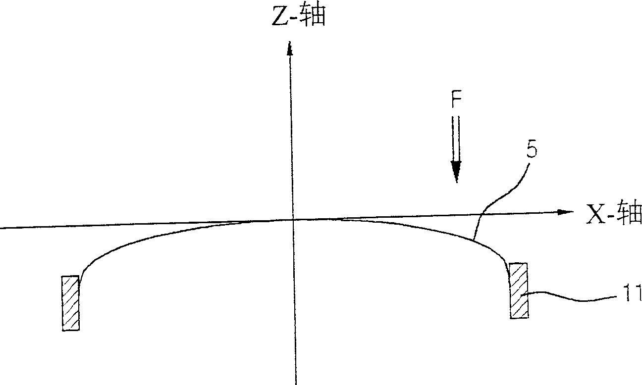
[0057] Figure 7 The radius of curvature of the shadow mask in the cathode ray tube according to the present invention is shown as a function of the distance from the center of the shadow mask.

[0058] refer to Figure 7 The radii of curvature of the shadow mask in the cathode ray tube of the present invention are substantially the same along the directions of the major axis, the minor axis and the diagonal axis respectively.

[0059] That is, as the distance from the center of the shadow mask increases, the radii of curvature in the respective directions (major axis, minor axis, and diagonal axis directions) do not differ greatly from each other, exhibiting substantially the same change.

[0060] with in Image 6 Compared with the results obtained from the prior art shadow mask shown in , the...


PUM


Abstract

A cathode ray tube comprises a panel having a fluorescent formed on an inner surface thereof; a funnel connected to the panel; an electron gun housed in the funnel emitting electron beams; a deflection yoke for deflecting the electron beams in horizontal and vertical directions; a shadow mask for selecting colors of the electron beams; and a mask frame for supporting the shadow mask, in which an outer surface of the panel is substantially flat and an inner surface has a designated curvature, and a radius of curvature from a center of the shadow mask in a major-axis, minor-axis and diagonal-axis direction is substantially same.

Description

technical field [0001] The present invention relates to a cathode ray tube, and more particularly, to a cathode ray tube including a shadow mask having improved drop characteristics by adjusting the curvature. Background technique [0002] figure 1 Shown is the structure of a prior art cathode ray tube. [0003] like figure 1 As shown in , the panel 1 and the funnel 2 of the color cathode ray tube are tightly sealed (or combined) together, so the inside of the cathode ray tube is usually in a vacuum state. [0004] Referring to the structure of the cathode ray tube, a fluorescent film 3 with red (R), green (G) and blue (B) three primary color phosphors (or fluorescent substances) is formed on the inside of the panel 1, and is connected to the fluorescent film at the neck of the funnel. The opposite side of the 3 is provided with an electron gun 4 for emitting electron beams 7 of three colors, namely red, green and blue. [0005] A shadow mask 5 having a color selection f...

Claims


Application Information

Patent Timeline
Patent Type & Authority Applications(China)
IPC IPC(8): H01J29/07H01J29/81H01J29/86
CPCH01J29/07H01J2229/0788
Inventor 金溶根
Owner LG PHILIPS DISPLAY KOREA CO LTD
Why Eureka
Try Eureka