Non-linear compensation circuit, transmission apparatus and non-linear compensation method
A non-linear compensation and non-linear technology, applied in the field of compensation circuits, can solve the problems that the distortion of the amplifier 303 cannot be fully compensated, and the compensation effect of the pre-corrector 301 is reduced, so as to achieve the effect of compensating the distortion
- Summary
- Abstract
- Description
- Claims
- Application Information
AI Technical Summary
Problems solved by technology
Method used
Image
Examples
no. 1 Embodiment
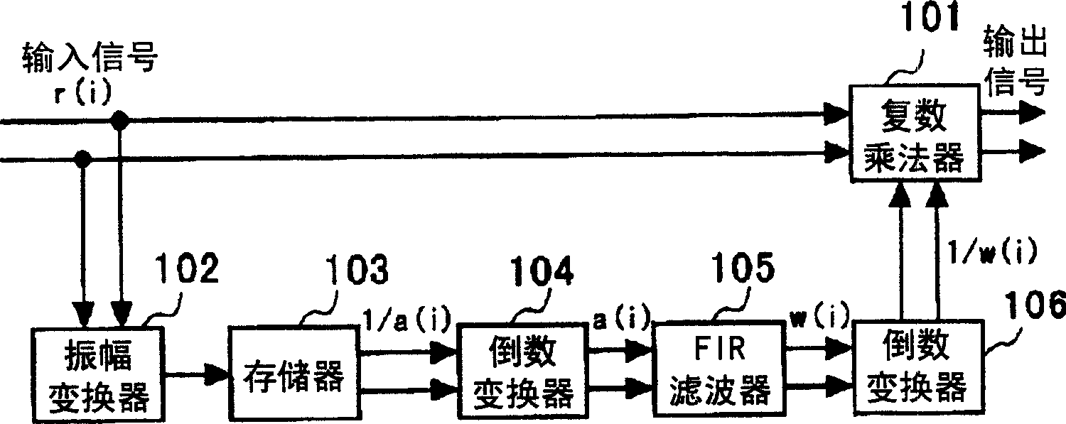
[0030] figure 1 A structural diagram showing a first embodiment of the present invention. figure 1 The structure shown, as a pre-orthodontator 301, is mounted on Image 6 shown in the transmitter.
[0031] refer to figure 1, the figure has: an amplitude converter 102, which inputs a complex baseband signal r(i) and outputs its amplitude; a memory 103, which stores and maintains the inverse characteristic of the input-to-output characteristic of the amplifier, constitutes a look-up table, and outputs the corresponding input address Inverse characteristic; the first reciprocal converter 104, which inputs the output from the memory 103 and outputs it, and outputs it after the reciprocal operation; FIR (finite impulse response) filter 105, which inputs the output signal of the first reciprocal converter 104, and performs filtering Output after operation; The 2nd reciprocal converter 106, the output of its input FIR filter 105, output after reciprocal operation; And complex n...
no. 2 Embodiment
[0062] Next, a second embodiment of the present invention will be described. Figure 4 It is a structural diagram showing the second embodiment. In this embodiment, the data stored in the memory 103' is used as the input-to-output characteristic of the amplifier, and thus also the gain characteristic of the amplifier. Therefore, it is possible to omit figure 1 The first reciprocal converter 104.
[0063] In this embodiment, the amplitude of the complex baseband signal is obtained by the amplitude converter 102, and the gain a(i) corresponding to the amplitude is output from the memory 103'. The FIR filter 105 performs filtering processing on the gain a(i). In the reciprocal converter 106, the reciprocal of the filtered gain w(t) is obtained. The complex multiplier 101 multiplies the complex baseband signal and the reciprocal output from the reciprocal converter 106 .
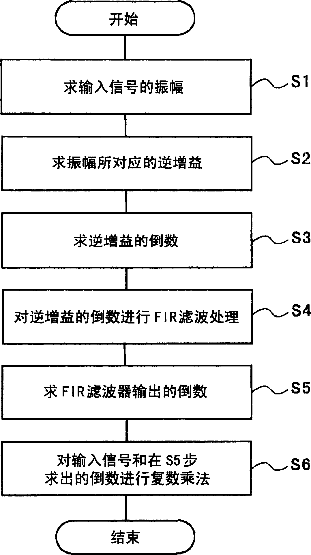
[0064] Figure 5 is explained in Figure 4 A flow chart of the processing procedure in the second emb...
PUM
 Abstract
Description
Claims
Application Information
 - R&D
- Intellectual Property
- Life Sciences
- Materials
- Tech Scout
- Unparalleled Data Quality
- Higher Quality Content
- 60% Fewer Hallucinations
Browse by: Latest US Patents, China's latest patents, Technical Efficacy Thesaurus, Application Domain, Technology Topic, Popular Technical Reports.
© 2025 PatSnap. All rights reserved.Legal|Privacy policy|Modern Slavery Act Transparency Statement|Sitemap|About US| Contact US: help@patsnap.com


