Pipe clamp

一种管夹、夹爪的技术,应用在管夹领域,能够解决会破坏、难以收紧、夹紧螺钉弯曲等问题

Inactive Publication Date: 2005-02-16
NORMA GERMANY GMBH
View PDF1 Cites 2 Cited by
  • Summary
  • Abstract
  • Description
  • Claims
  • Application Information

AI Technical Summary

Problems solved by technology

In extreme cases, the clamping screw may bend when the clamp is tightened; this may make tightening more difficult
Welding the jaws is not only complicated, but also destroys the optional protective layer on the clamping strip for corrosion protection

Method used


Image

  • Pipe clamp
  • Pipe clamp
  • Pipe clamp

Examples


Embodiment Construction

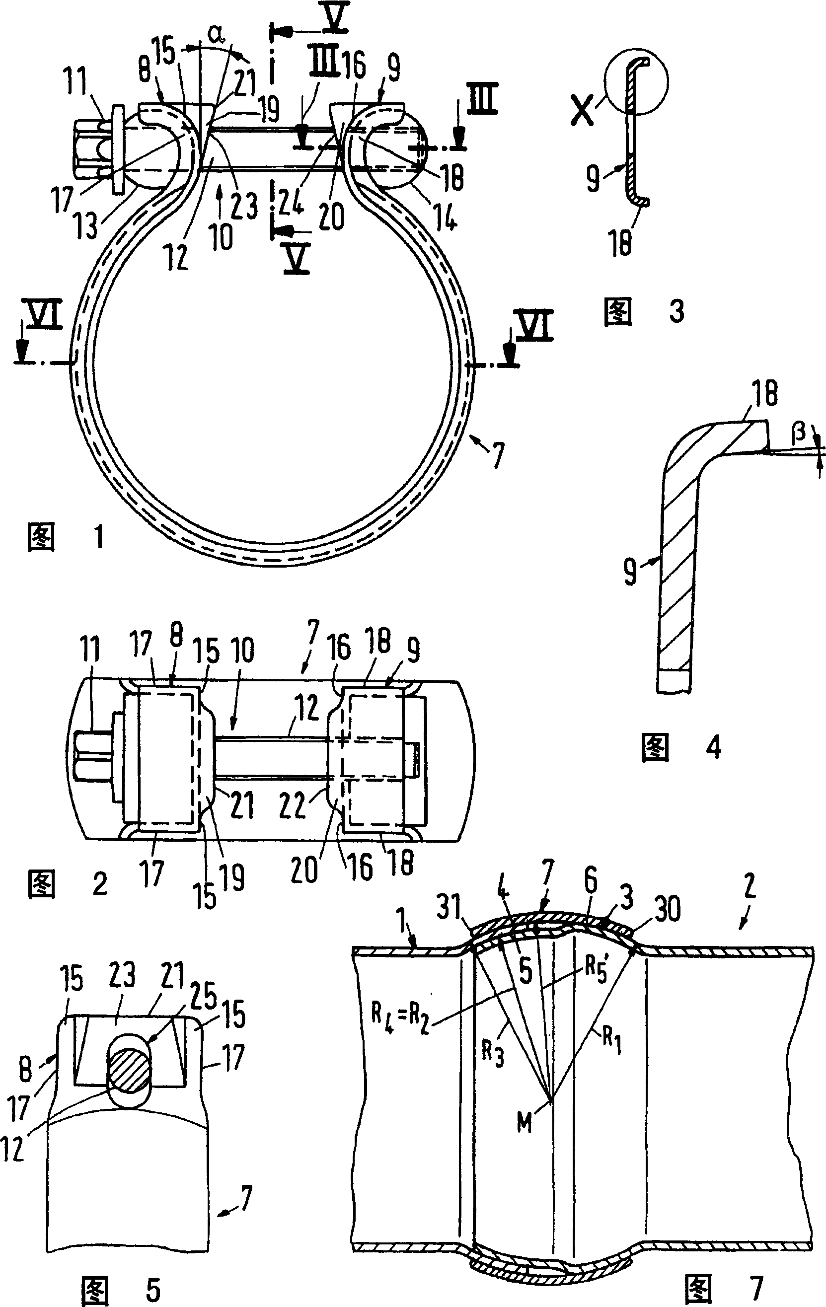
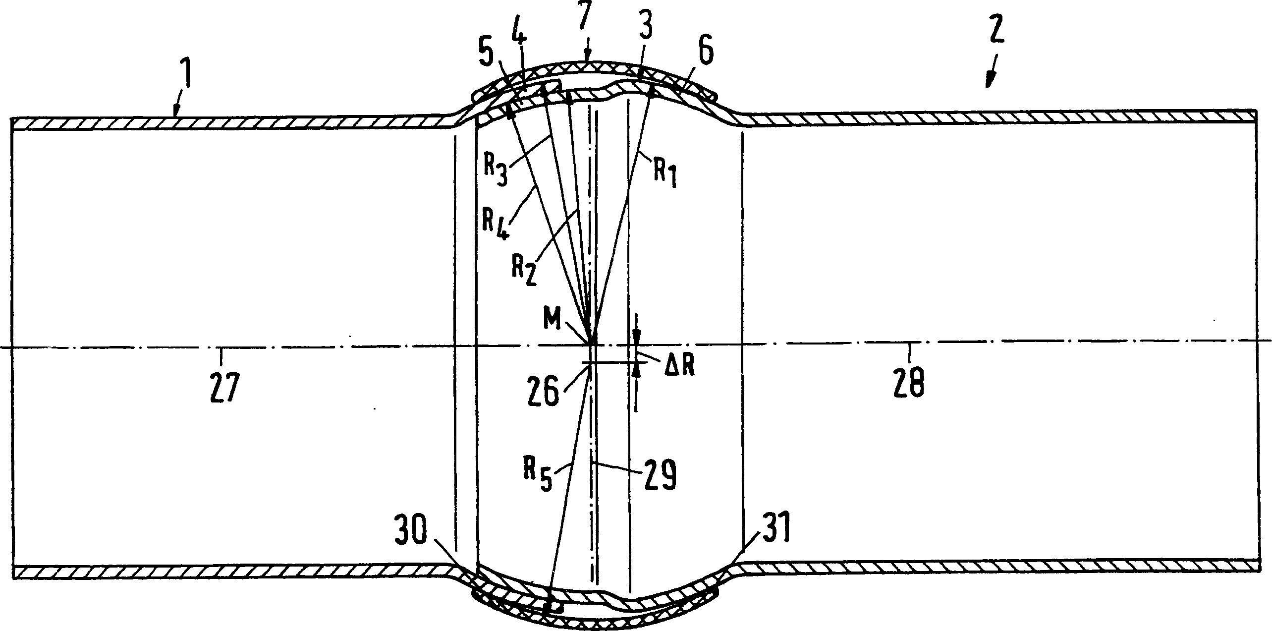
[0036] The pipe clips according to FIGS. 1 to 7 are used to connect two pipes 1 and 2 of an exhaust system of a motor vehicle. Tubes 1 and 2 have ends that can be partially plugged together: an insertion end 3 and a receiving end 4 . Insertion ends are made with different outer radii R 1 and R 2 Two spherical regions 5 and 6 are formed. The receiving end 4 is formed by only one spherical area with an outer radius R 3 with the outer radius R of the spherical area 6 1 same, its inner radius R 4 with the outer radius R of the spherical area 5 2 same. The purpose of these spherical areas is to position the tubes 1 and 2 in position before tightening the tube clamps, where the two tubes are at a slight angle to each other.

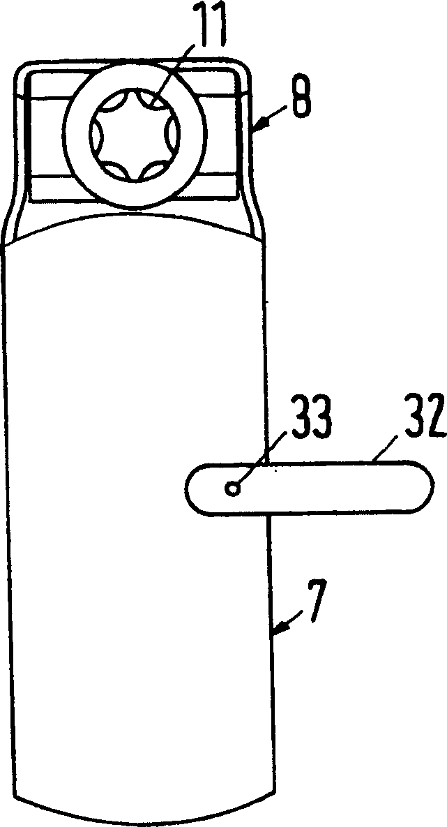
[0037]The pipe clamp according to FIGS. 1 to 7 has a clamping strip 7 which has an outwardly bent barrel shape in the axial direction, the ends of which are formed as clamping jaws 8 and 9 . Thus, jaws 8 and 9 are integrally formed with entrainment stri...


PUM


Abstract

Pipe clip has a transverse axis (26) around which a tensioned clip band (7) is bent at a distance (DELTAR) from the middle point of ball zones (4, 5, 6). The inner radius of the bent of the tensioned clip band around the transverse axis is smaller than the outer radius of the ball zones so that the sum of the distance (DELTAR) and the inner radius of the bend is larger than the outer radius of the ball zones. An Independent claim is also included for a connecting arrangement of two pipes and the pipe clip. Preferred Features: The inner peripheral edges (30, 31) of the clip band are rounded.

Description

technical field [0001] The invention relates to a pipe clamp for connecting two pipes, in particular pipes of automobile exhaust pipes. The tubes are partially insertable into each other and have an insertion end and a receiving end. The insertion end is divided into two spherical regions, wherein the outer radius of the first spherical region adjoining the free end of the insertion end is the same as the inner radius of the receiving end. The receiving end is also made as a spherical area, and the insertion end can be inserted into the receiving end. The outer radius of the second spherical region of the insertion end is the same as the outer radius of the receiving end. The tube clamp includes a band that encloses the receiving end and the second bulbous region when the tubes are inserted one inside the other. The entrainment bands are bent about a transverse axis which lies in an entrainment center plane perpendicular to the coaxial central axis of the tubes when the tub...

Claims


Application Information

Patent Timeline
Patent Type & Authority Applications(China)
IPC IPC(8): F01N13/08B25B5/06F01N13/18F16B2/08F16B7/04F16L21/06F16L21/08F16L27/04
CPCF01N13/185F16L27/04F01N13/1805F01N2450/24F01N13/1822F16L21/08F16L21/06
Inventor H·格佩尔特H·P·沃尔夫S·曼M·索默
Owner NORMA GERMANY GMBH
Why Eureka
Try Eureka