Tape winding method
A tape and reel technology, applied in the direction of winding strips, magazine/cassette tape manufacturing equipment, thin material processing, etc., can solve problems such as difficult tape winding habits, so that it is not easy to wind unevenly, walk Highly stable effect
- Summary
- Abstract
- Description
- Claims
- Application Information
AI Technical Summary
Problems solved by technology
Method used
Image

Examples
no. 1 Embodiment approach
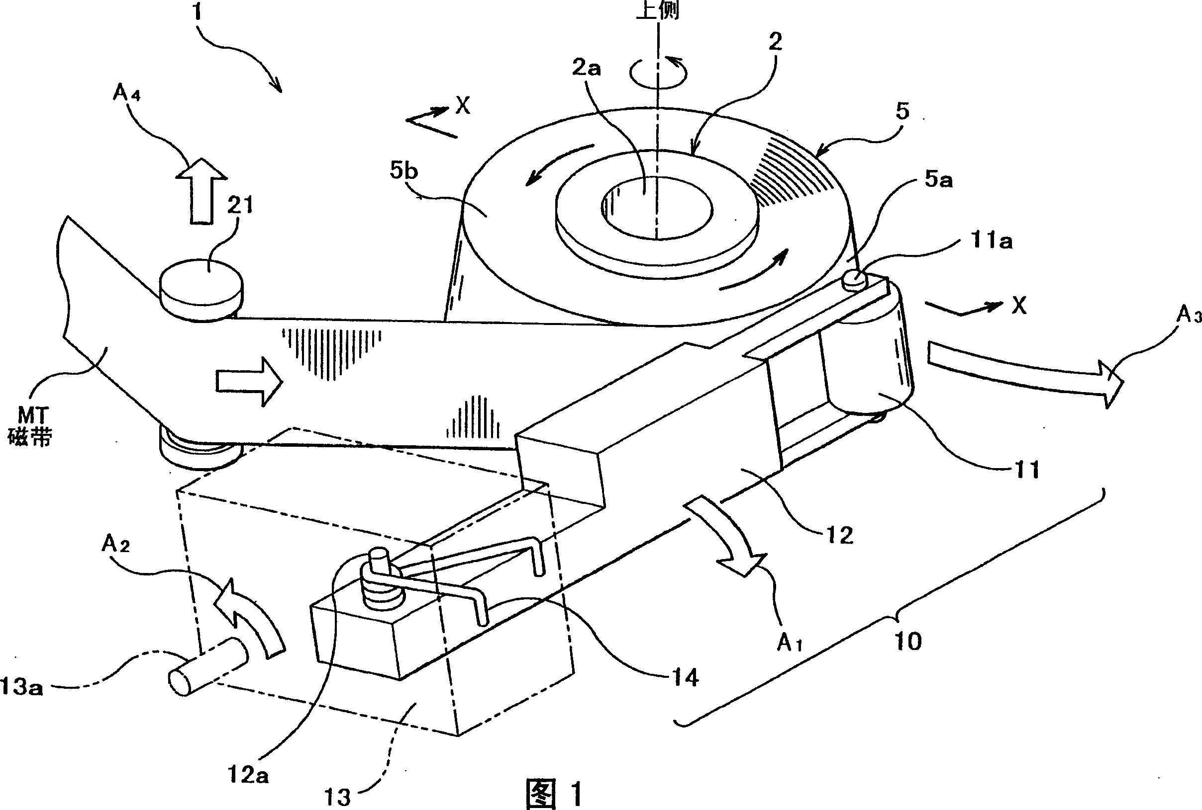
[0050] Below, refer to Figure 1- Image 6 , the tape winding method according to the first embodiment will be described.
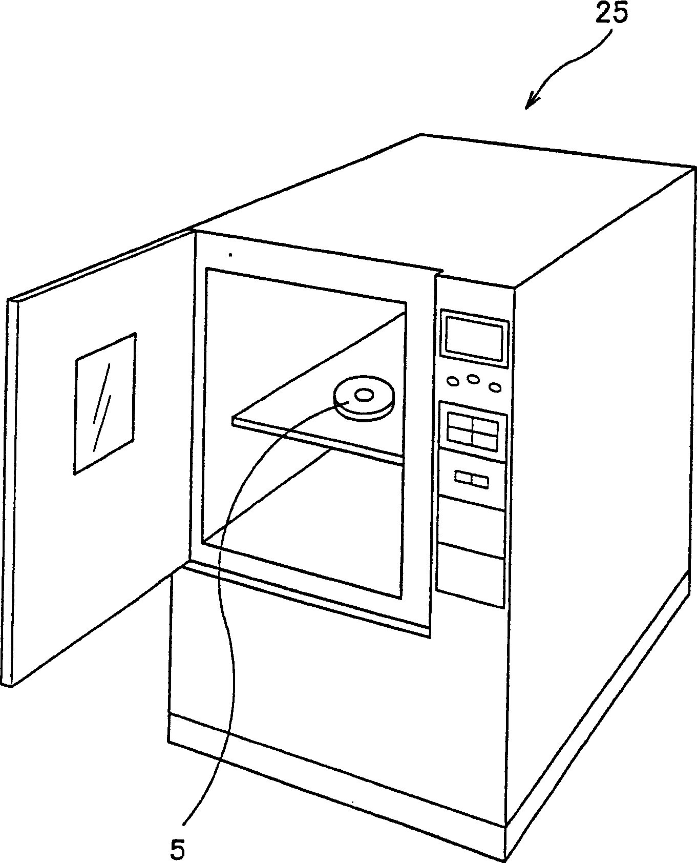
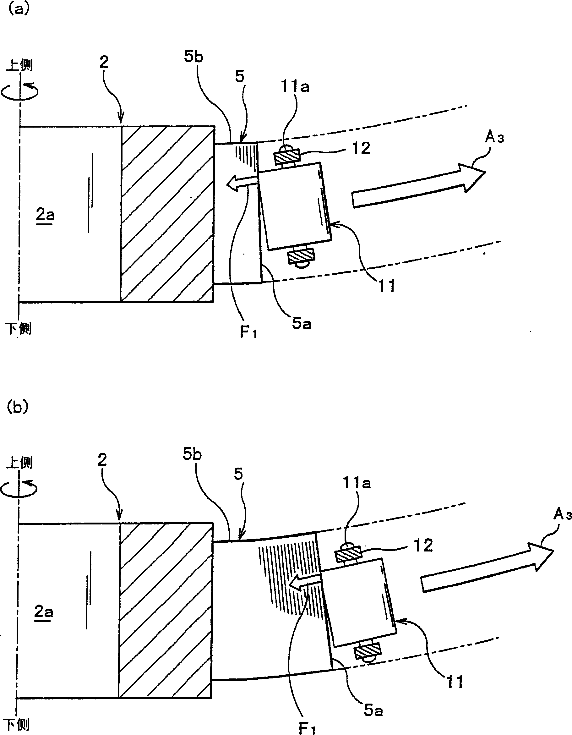
[0051] Among the drawings referred to, FIG. 1 is a perspective view showing the overall structure of a winding device used in the tape winding method according to the first embodiment. figure 2 It is a perspective view showing the overall structure of the heat treatment apparatus used in the tape winding method according to the first embodiment. image 3 (a) is a partial cross-sectional view schematically showing the winding state in the initial stage of winding in the X-X cross section shown in FIG. 1 . image 3 (b) is schematically indicated at image 3 (a) Thereafter, a partial cross-sectional view of the winding state in the mid-winding stage in which winding is continued. Figure 4 (a) is schematically indicated at image 3 (b) Partial front view of the tension generated by the magnetic tape in the mid-winding stage shown. Figure 4 (b) is a part...
no. 2 Embodiment approach
[0109] Below, refer to the appropriate Figure 7 and Figure 8 , and the tape winding method according to the second embodiment will be described.
[0110] In the referenced figure, Figure 7 It is a perspective view showing the overall structure of the winding device used in the tape winding method according to the second embodiment. Figure 8 (a) is a schematic representation Figure 7 In the Z-Z section shown, a partial cross-sectional view of the winding state in the initial stage of winding. Figure 8 (b) is a partial cross-sectional view schematically showing the winding state in the middle of winding in which winding is continued.
[0111] The tape winding method according to the second embodiment differs from the tape winding method according to the first embodiment only in the winding step. More specifically, depending on the structure of the winding device, the method of winding the magnetic tape MT onto the shaft 2 is also different. In the first embodiment, w...
no. 3 Embodiment approach
[0123]Next, referring to FIG. 9 , the tape winding method according to the third embodiment will be described.
[0124] Of the figures referred to, FIG. 9( a ) is a front view showing the overall structure of a winding device used in the tape winding method according to the third embodiment, and schematically showing the winding state in the initial stage of winding. FIG. 9( b ) is a front view schematically showing a winding state in a later stage of winding in which winding is continued after FIG. 9( a ).
[0125] The tape winding method according to the third embodiment is different from the tape winding method according to the first embodiment only in the winding step. More specifically, depending on the structure of the winding device, the method of winding the magnetic tape MT onto the shaft 2 is also different. In the third embodiment, instead of using the coil outer peripheral surface pressing member 10 according to the first embodiment, a winding guide 51 having a gu...
PUM
 Abstract
Description
Claims
Application Information
 - R&D
- Intellectual Property
- Life Sciences
- Materials
- Tech Scout
- Unparalleled Data Quality
- Higher Quality Content
- 60% Fewer Hallucinations
Browse by: Latest US Patents, China's latest patents, Technical Efficacy Thesaurus, Application Domain, Technology Topic, Popular Technical Reports.
© 2025 PatSnap. All rights reserved.Legal|Privacy policy|Modern Slavery Act Transparency Statement|Sitemap|About US| Contact US: help@patsnap.com