Rib shaping mould

A technology of forming die and wire hook, applied in the field of machinery, can solve the problems of low production efficiency, high processing cost, many production equipment, etc., and achieve the effect of fast production speed, high work efficiency, and automatic production.

Inactive Publication Date: 2005-02-23
ZHEJIANG TOPSUN LOGISTIC CONTROL CO LTD
View PDF0 Cites 13 Cited by
  • Summary
  • Abstract
  • Description
  • Claims
  • Application Information

AI Technical Summary

Problems solved by technology

These four processes are completed through independent production equipment and different molds, requiring more production equipment and occupying a large area
At the same time, since these four processes are

Method used


Image

  • Rib shaping mould
  • Rib shaping mould
  • Rib shaping mould

Examples


Embodiment Construction

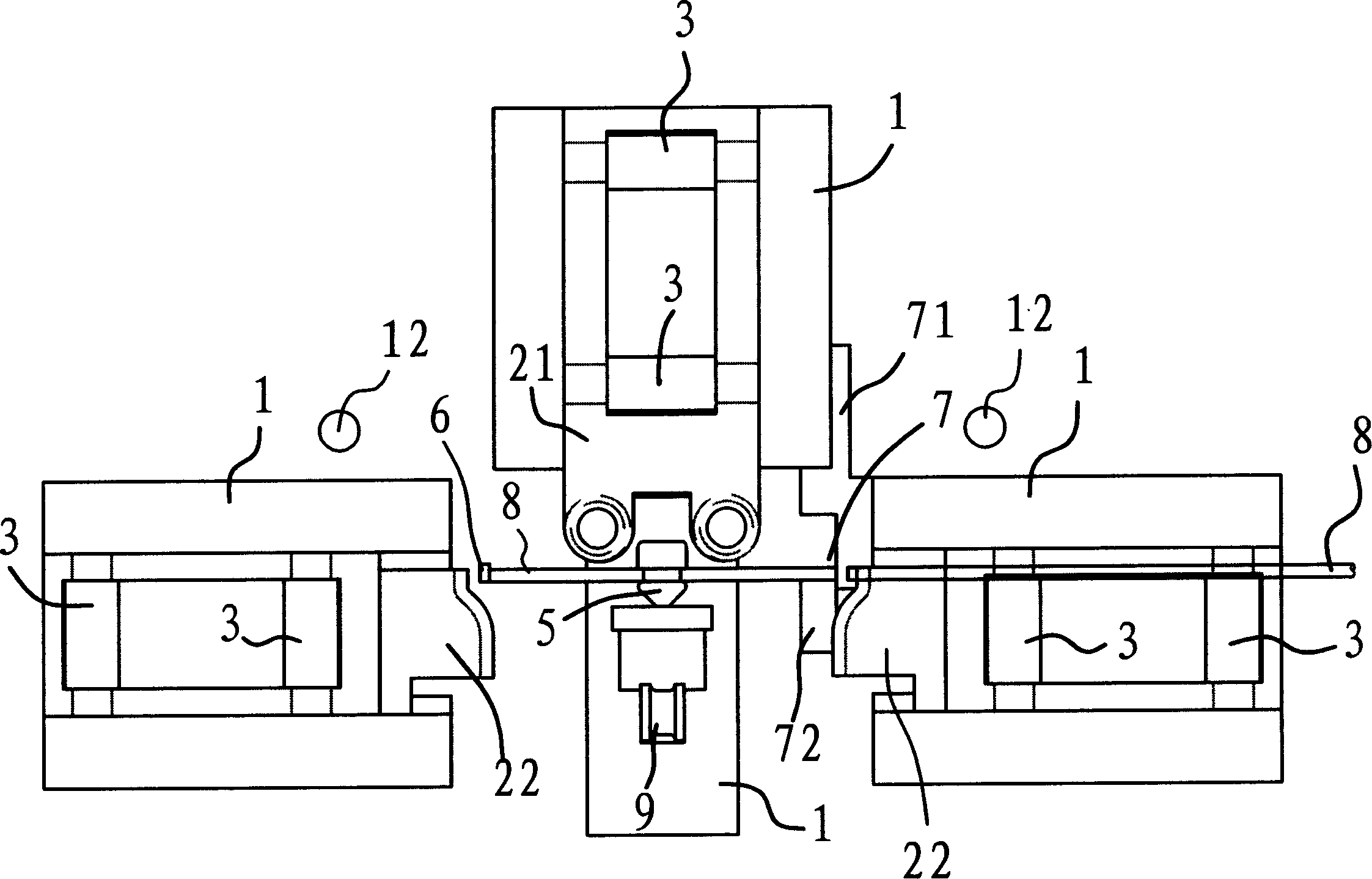
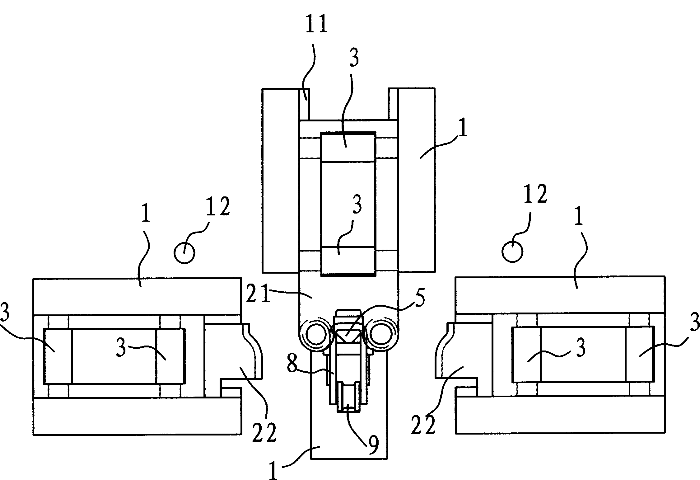
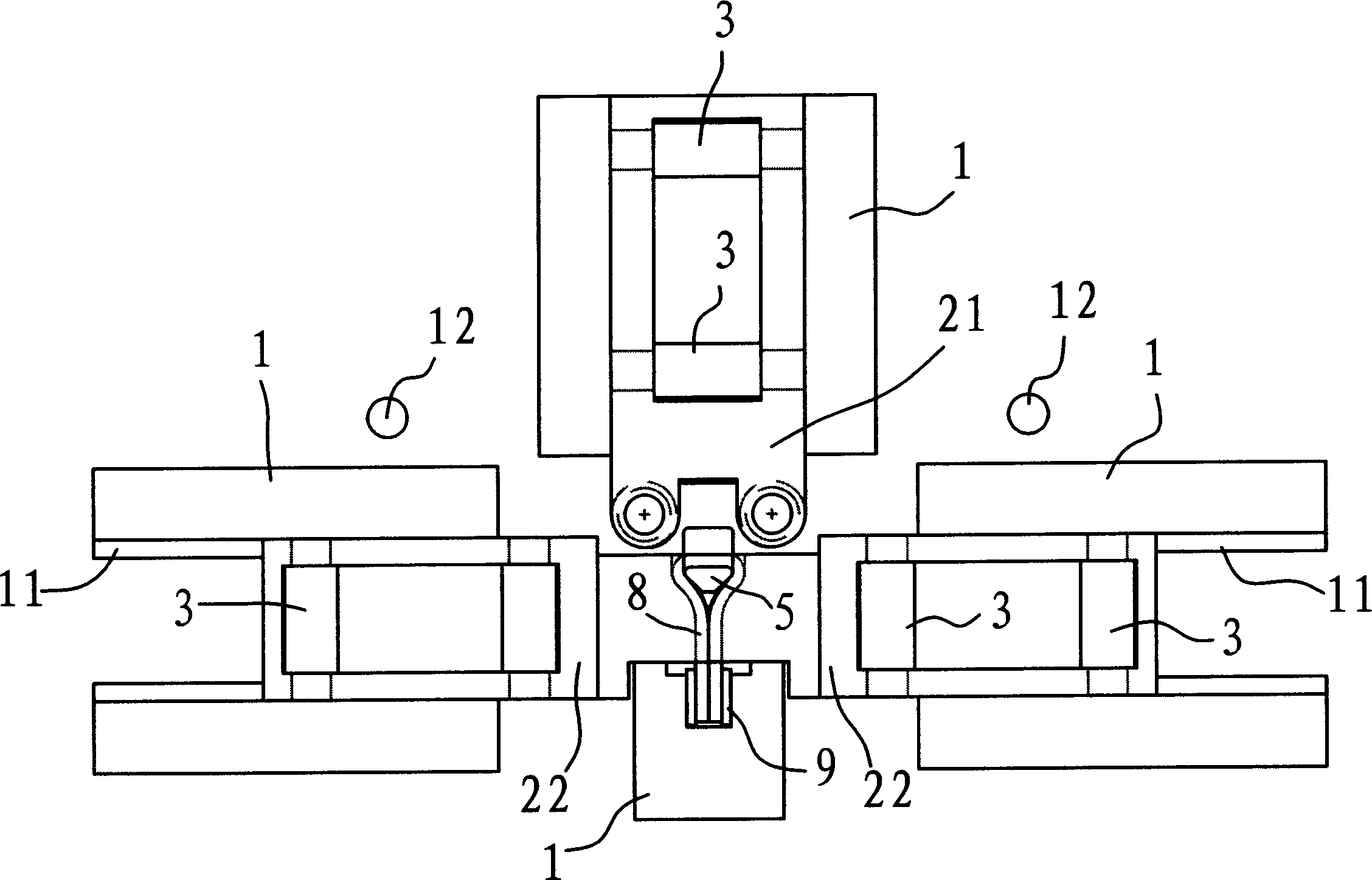
[0022] Such as figure 1 , figure 2 , image 3 and Figure 4 As shown, the wire hook forming mold includes a base 1, a mold core 5 and each slider 2, wherein the slider 2 has a U-shaped slider 21 above the mold core 5, and two pressing joints on the left and right sides of the mold core 5. The slide block 22 and the forming punch 42 that is in front of the die core 5 . In this embodiment, the wire hook forming die also includes a wire cutting device 7 . The device 7 is made up of a lower die 72 below the wire rod 8 and an upper die 71 above the wire rod 8 , the lower die 72 is fixed on the base 1 , and the upper die 71 is fixed on the U-shaped slide block 21 .

[0023] Such as figure 1 As shown, a positioning plate 6 is provided on the other side of the U-shaped slider 21 , and the positioning plate 6 is fixed on the base 1 . After the wire rod 8 passed through the notch 51 of the cutting device 7 and the mold core 5 , its front end pressed against the positioning plat...


PUM


Abstract

A wire hook forming mould is composed of a base, a core with a notch for passing the wire through it, a U-shaped slide block above said core, a pair of left and right pressing slide blocks at both sides of core, a shaping punch head in the front of core, a controller for all the slide blocks and a wire cutter.

Description

technical field [0001] The invention belongs to the technical field of machinery, and in particular relates to a forming die for production line hooks. Background technique [0002] The wire hook is an indispensable part of instruments such as binders and belt tighteners. The shape of the hook is as Figure 9-1 and Figure 9-2 As shown, the wire hook is formed by stamping and bending a metal wire or plate. [0003] At present, four processes are generally used in the production of wire hooks, namely, material cutting, bending into a U shape, pressing and bending. These four processes are completed through independent production equipment and different molds, which require more production equipment and occupy a large area of ​​the site. At the same time, since these four processes are completed on different punching machines, the semi-finished product needs to be constantly changed to the processing location, the production efficiency is low, and the pro...

Claims


Application Information

Patent Timeline
IPC IPC(8): B21F45/16
Inventor 阮卜琴
Owner ZHEJIANG TOPSUN LOGISTIC CONTROL CO LTD
Why Eureka
Try Eureka