Electric rheological fluid vibration-absorber for vehicle engine

A technology of automobile engine and electrorheological fluid, which is applied in the direction of power plant, vehicle parts, vibration suppression adjustment, etc., can solve the problems of rigidity, damping unadjustable, narrow vibration frequency range, and affecting the service life of the vehicle for ride comfort, etc., to achieve Reducing ride discomfort and satisfying effect

Inactive Publication Date: 2005-02-23
ZHEJIANG UNIV
View PDF0 Cites 23 Cited by
  • Summary
  • Abstract
  • Description
  • Claims
  • Application Information

AI Technical Summary

Problems solved by technology

The stiffness and damping of these damping devices cannot be adjusted after they are installed on the engine suspension, and the range of vibration fre

Method used


Image

  • Electric rheological fluid vibration-absorber for vehicle engine

Examples


Embodiment Construction

[0007] This embodiment is an electrorheological fluid shock absorber used in automobile engines.

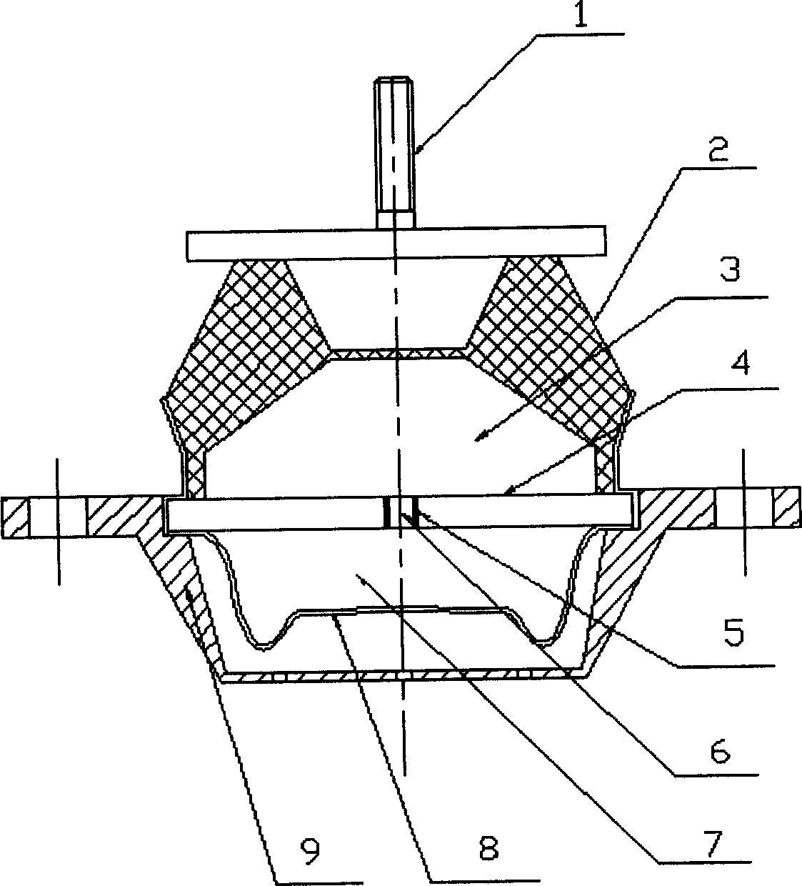
[0008] Such as figure 1 As shown, the main structure of this embodiment is: central bolt 1, upper end cover 2, upper working chamber 3, separator 4, electrode 5, damping channel 6, lower working chamber 7, elastic membrane 8, lower end cover 9.

[0009] Embodiments of the present invention will be described in detail below in conjunction with the accompanying drawings.

[0010] The upper working chamber 3 with electrorheological fluid, which is composed of the upper end cover 2 and the partition plate 4 made of elastic material, is the elastic element of the vibration damping system. When it is subjected to external excitation, it can deform and change the upper working chamber. The volume of the cavity allows the electrorheological fluid to be discharged through the damping channel 6. Obviously, if the oil discharge of the upper working chamber is unobstructed, the stiffness o...


PUM


Abstract

A vibration damper using electric rheopectic liquid for the engine of car features that a pair of electrode connected to high-voltage power supply is installed at both sides of a rectangular damping channel full of electric rheopectic liquid, and regulating the output voltage of said high-voltage power supply can change the electric field intensity between two electrodes and in turn the viscosity of electric rheopectic liquid, so regulating the damping effect.

Description

technical field [0001] The invention belongs to a vibration damping device of an engine, in particular to a vibration damping system used for an automobile engine support. Background technique [0002] At present, most of the engine mounts on automobiles use rubber support, spiral steel wire rope and hydraulic support, which is the so-called passive damping system. The stiffness and damping of these damping devices cannot be adjusted after they are installed on the engine suspension, and the range of vibration frequencies that can be suppressed is relatively narrow. The corresponding parameters affect the ride comfort and the service life of the vehicle. [0003] The object of the present invention is an electrorheological fluid shock absorber for an engine designed to avoid the above-mentioned deficiencies in the prior art. It effectively controls the liquid in the shock absorber through an external electric field, thereby changing its stiffness and damping, so as to achi...

Claims


Application Information

Patent Timeline
IPC IPC(8): B60K5/00F16F9/53
Inventor 许沧粟郦光明
Owner ZHEJIANG UNIV
Why Eureka
Try Eureka