

Linea encoder
A linear encoder and sleeve technology, applied in the field of linear encoders, can solve the problems of positioning accuracy influence, deformation, unfavorable sliding body 120 and main grating ruler 150 maintaining the position and distance, etc.
- Summary
- Abstract
- Description
- Claims
- Application Information
AI Technical Summary
Problems solved by technology
Method used
Image

Examples
Embodiment 1
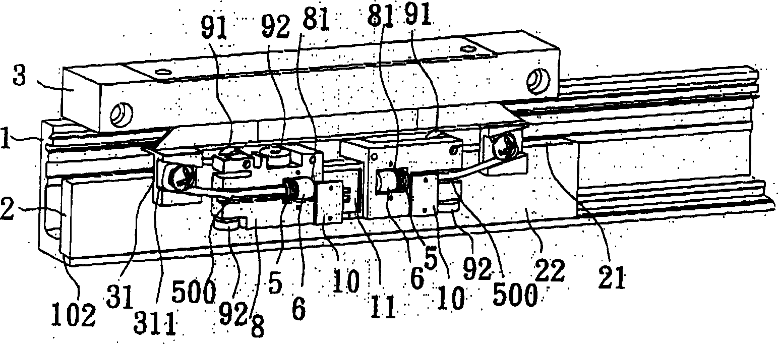
[0044] The linear encoder of the present invention such as image 3 As shown, in this embodiment, it includes a main grating ruler 2 with a front reference surface 22 and an end reference surface 21; a main housing 1 with a slot 102, wherein the slot 102 is arranged in the main housing The bottom of the body 1, and the main grating scale 2 is placed on the slot 102, so that the front reference surface 22 and the end reference surface 21 of the main grating scale 2 are not facing the main housing; a sliding body 8 has two sleeves Bearing groove 81, two cover plates 10, three rolling bearings 92 in contact with the front reference surface 22, and two rolling bearings 91 in contact with the end surface reference surface 21, these rolling bearings 91, 92 are pasted on the main grating scale 2 , so that the sliding body 8 moves parallel to the main grating scale 2; a marked grating scale 11 is located in the middle of the two sleeve bearing grooves 81 of the sliding body 8, so that...
Embodiment 2
[0049] The linear encoder of the present invention is roughly the same as Embodiment 1 in this embodiment, and the only difference from Embodiment 1 is the compression connection mechanism 500, such as Figure 6 shown.
[0050] Two groups of compression coupling mechanisms 501 and 502 in this embodiment, one group 501 includes a spherical ball (not shown in the figure) in the sleeve seat slot 81, which can rotate freely; Cover the cylindrical sleeve 6 on the periphery of the spherical bead 7, and can rotate freely; a spring steel wire 4, one end of which is connected with the protruding arm of the circuit box (not shown in the figure), and the other end is connected with the cylindrical sleeve 6 , so that the circuit box is connected to the sliding body 8; and a compression spring 5 that presses the cylindrical sleeve 6, so that the spherical beads 7 in the cylindrical sleeve 6 can withstand the groove of the sleeve seat of the sliding body 8 81; while the other group 502 onl...
Embodiment 3
[0053] The linear encoder of the present invention such as Figure 7 As shown, this embodiment includes a main grating scale 2 with a front reference surface 22 and an end reference surface 21; a main housing 1 with a slot 102, wherein the slot 102 is arranged in the main housing 1, and the main grating ruler 2 is placed on the slot 102, so that the front reference surface 22 and the end reference surface 21 of the main grating ruler 2 are not facing the main housing; a sliding body 8 has a sleeve seat Notch 81, three rolling bearings 92 in contact with the front reference surface 22, and two rolling bearings 91 in contact with the end surface reference surface 21, these rolling bearings 91, 92 make the sliding body 8 move in parallel along the main grating scale 2; a marking grating Ruler 11, located on one side of the sliding body 8, the marked grating ruler 11 cooperates with the main grating ruler 2 to generate a light diffraction to measure the displacement distance; a ci...
PUM
 Abstract
Description
Claims
Application Information