Method for realizing multiple path optical scanning using single mode optical fiber

A single-mode optical fiber and optical scanning technology, which is applied in phototypesetting devices, printing, phototypesetting devices, etc., can solve problems such as unsatisfactory spot shape, difficulty in consistent spot shape, difficulty in meeting scanning quality requirements, etc.

Inactive Publication Date: 2005-03-02
深圳市东方宇之光科技股份有限公司
View PDF0 Cites 3 Cited by
  • Summary
  • Abstract
  • Description
  • Claims
  • Application Information

AI Technical Summary

Problems solved by technology

[0005] In fact, even if the focus is accurate, the shape of the light spot is not ideal, and the shape of the light spots is still difficult to be consistent
Even with screening of the spot pattern at the coupling stage, it is difficult to meet the scan quality requirements

Method used


Image

  • Method for realizing multiple path optical scanning using single mode optical fiber
  • Method for realizing multiple path optical scanning using single mode optical fiber
  • Method for realizing multiple path optical scanning using single mode optical fiber

Examples


Embodiment Construction

[0032] The present invention will be further described below in conjunction with accompanying drawing:

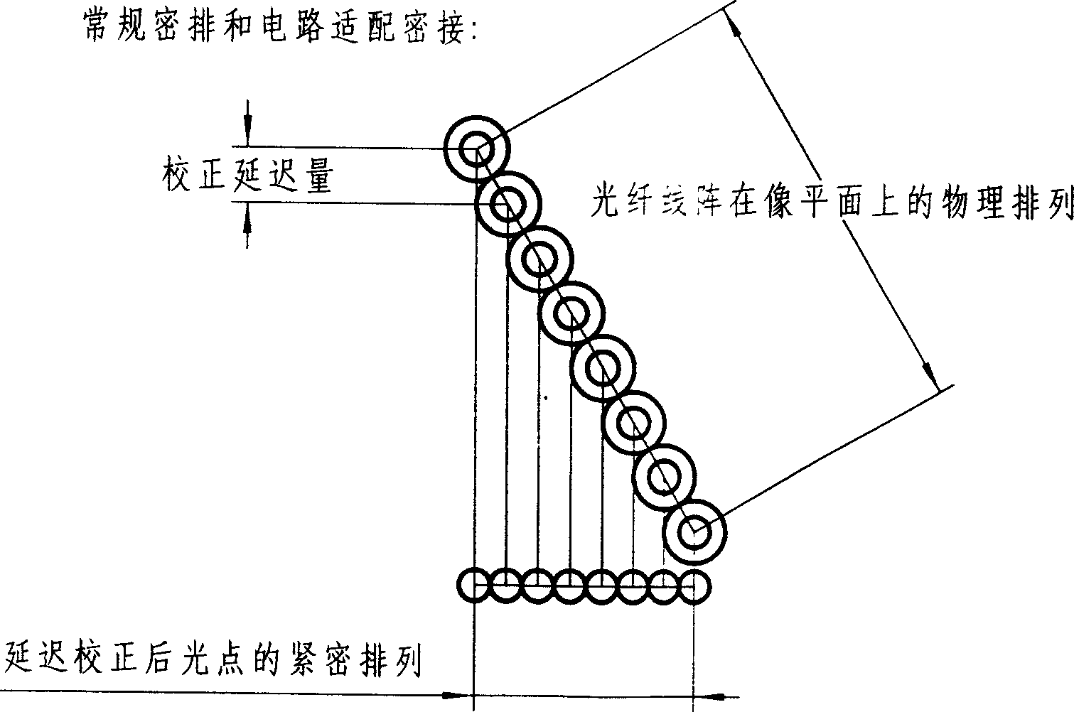
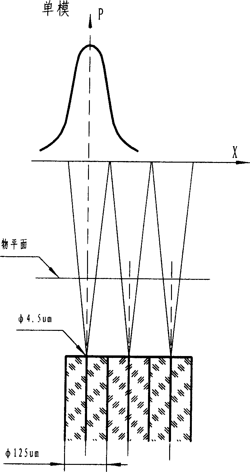
[0033] The solution proposed by the present invention is to adopt single-mode optical fibers to be arranged close-packed (inclined close-packed) according to the outer diameter, but to abandon the conventional imaging concept, that is, to still use a reduction (such as 1:5) lens, but not to use the end face of the optical fiber as the window. Instead of placing the object plane at an appropriate distance after exiting the window, the light spot of the single-mode fiber will have a suitable enlarged size on the object plane (due to defocus), while the distance between the light spots is Reduced (due to lens magnification). This will make it possible to use the circuit adaptation method to closely connect the light spots. It is even possible to use a lens with a smaller magnification, such as 1:10, to directly close the light spot by defocusing without circuit adaptation (bu...


PUM


Abstract

The method of realizing multipath light scanning with single-mode fiber includes setting closely arranged linear fiber array obliquely and setting the object plane in proper position behind the window to makes it possible to closely contact light spots via adapting circuit. The circuit part includes monostable delay counter A, trigger D, bit frequency divider U3, first-in-first-out asynchronous read / write queue memory FIFO, etc. The key point of the present invention is to utilize the characteristic that the outgoing light beam of single-mode fiber in the object plane has expanded diameter but complete edge to realize the close contact of light spots and the uniformity of different light spot modes and to reach light spot array quality much higher than that of multi-mode fiber.

Description

technical field [0001] The invention relates to the optical fiber close-arranged line array technology in a laser phototypesetting system, mainly referring to a method for realizing multi-path light scanning with a single-mode optical fiber. Background technique [0002] One of the methods to realize multi-channel light scanning in laser phototypesetting machine and laser photoplotter is to use semiconductor laser as the primary light source, couple it into the optical fiber, and then arrange the optical fiber into a multi-line array as the secondary light source. [0003] At present, multimode optical fibers are used to achieve close packing. Because the multimode optical fiber has a suitable diameter of the light export window, it is easy to realize the tight connection of the light spots. The inner diameter (light export window) of commonly used multimode fiber is generally 62.5um or 50um, and the outer diameter is 125um. There are two ways to achieve tight connection: ...

Claims


Application Information

Patent Timeline
Patent Type & Authority Applications(China)
IPC IPC(8): B41B19/00B41B21/08
Inventor 刘晓东
Owner 深圳市东方宇之光科技股份有限公司
Why Eureka
Try Eureka