Rotary tubular photo-catalytic reactor and its water treating method

A photocatalytic reactor and rotating drum technology, applied in the direction of light water/sewage treatment, etc., can solve problems such as affecting the processing capacity of the reactor, and achieve the effects of small footprint, low energy consumption, and fast update speed.

Inactive Publication Date: 2005-03-02
TIANJIN UNIVERSITY OF TECHNOLOGY
View PDF2 Cites 29 Cited by
  • Summary
  • Abstract
  • Description
  • Claims
  • Application Information

AI Technical Summary

Problems solved by technology

The common feature of the existing reactors is that the main part of the reactor is static, and the distribution of the treatment liquid and the catalyst is adjusted depending on the fluid flow rate and the amount of catalyst added or loaded. This adjustment method will affect The throughput of the reactor

Method used


Image

  • Rotary tubular photo-catalytic reactor and its water treating method
  • Rotary tubular photo-catalytic reactor and its water treating method
  • Rotary tubular photo-catalytic reactor and its water treating method

Examples


Embodiment 1

[0032] Add 5L of 4BS direct dye with an initial concentration of 5mg / L to the first drum type photocatalytic reactor, and after 7 hours of reaction, the decolorization rate of 4BS dye reaches 63.98%.

Embodiment 2

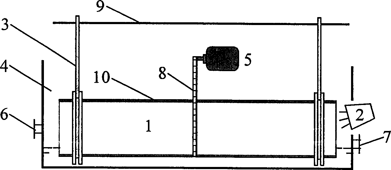
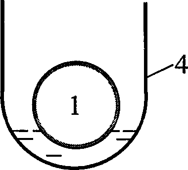
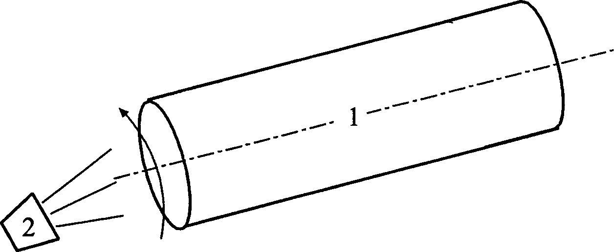
[0034] A method for treating water, comprising the steps of: (1) adding TiO containing TiO in the second drum type photocatalytic reactor 2 The waste water of catalyst fine powder, described rotary drum type photocatalytic reactor, comprises water tank 17, ultraviolet lamp 12, rotating drum 11, is provided with water inlet 14 and water outlet 15 on the water tank 17, and one end of rotating drum 11 passes central axis and The support frame 16 is connected, and the other end of the drum 11 is connected with the speed regulating motor 18 through the central shaft and the support frame 16. Parallel, a reflector 13 is arranged above the ultraviolet lamp 12; (2) 1 / 3~1 / 2 of the vertical height of the drum 11 is immersed in the waste water, and the speed regulating motor 18 is started, and the speed regulating motor drives the reactor drum 11 rotates to form a layer of liquid film with adjustable thickness on the outer surface of the drum; (3) turn on the ultraviolet lamp 12 to allow...

Embodiment 3

[0036] The steps of the method adopted are the same as in Example 2, and the dosage ratio of the catalyst in the waste water is: 1.2g / L.


PUM

PropertyMeasurementUnit
radiusaaaaaaaaaa
areaaaaaaaaaaa

Abstract

The rotary tubular photocatalytic reactor includes water trough with water inlet and water outlet, ultraviolet lamp set onto side of the water trough, rotary drum, which has bearing plates and supports in two ends and is set inside the water trough, speed regulating motor meshed to gear on the outer wall of the rotary drum for driving, and thin titania photocatalyst layer painted to the inner wall of the water trough. The present invention has rotary drum as the main body of the reactor and titania photocatalyst layer loaded onto the rotary drum, regulates the rotation speed of the rotary drum to alter the distribution of treated waste water and photocatalyst and to increase the contact area between the catalyst, reactant and light source, and has low power consumption, low treating cost, mild treating condition and other advantages.

Description

technical field [0001] The invention relates to a photocatalytic water treatment reaction device and a related treatment method. Background technique [0002] Photocatalytic water treatment technology is moving from laboratory to practical application due to its wide applicability and high efficiency. At this time, reactor design has become an important link in whether this technology can be industrialized. The photocatalytic water treatment reactor integrates the light source, catalyst and treatment liquid, and can make it a place to maximize the photocatalytic reaction to treat sewage. Therefore, it should have the ability to fully contact the catalyst, treatment liquid, and photons. basic features. High treatment intensity, low treatment cost and wide adaptability are the basic requirements for photocatalytic water treatment reactors. [0003] At present, there are two main types of photocatalytic water treatment reactors: one is a fixed-bed reactor (including a membra...

Claims


Application Information

Patent Timeline
Patent Type & Authority Applications(China)
IPC IPC(8): C02F1/32
Inventor 尹晓红辛峰张凤宝王世铭张国亮
Owner TIANJIN UNIVERSITY OF TECHNOLOGY
Why Eureka
Try Eureka