Eureka AIR delivers breakthrough ideas for toughest innovation challenges, trusted by R&D personnel around the world.

Three phase voltage-stabilizing controller and its control method

A control device and voltage stabilization technology, applied in the direction of reactive power adjustment/elimination/compensation, reactive power compensation, etc., can solve the problems of easy to burn out coils, increased energy consumption, and high cost

Inactive Publication Date: 2005-03-02
NANNING OUDING ELECTRIC +1
View PDF0 Cites 11 Cited by
  • Summary
  • Abstract
  • Description
  • Claims
  • Application Information

AI Technical Summary

Problems solved by technology

The current voltage regulating and stabilizing devices are mainly servo-type voltage regulating methods, and the servo motor type uses carbon brushes for voltage regulation, and the phenomenon of arcing when the carbon brush replaces the thread end slot is easy to burn out the coil and has a high failure rate. It is not suitable for use in relatively harsh environments, which will reduce the operating performance and service life of electrical equipment, and even cause some equipment with strict voltage requirements to fail to work normally, and will also greatly increase energy consumption. The current voltage regulation technology and products have complex structure, poor reliability and high cost, which hinder the wide application of voltage regulation technology.

Method used

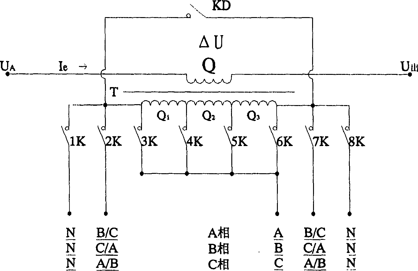
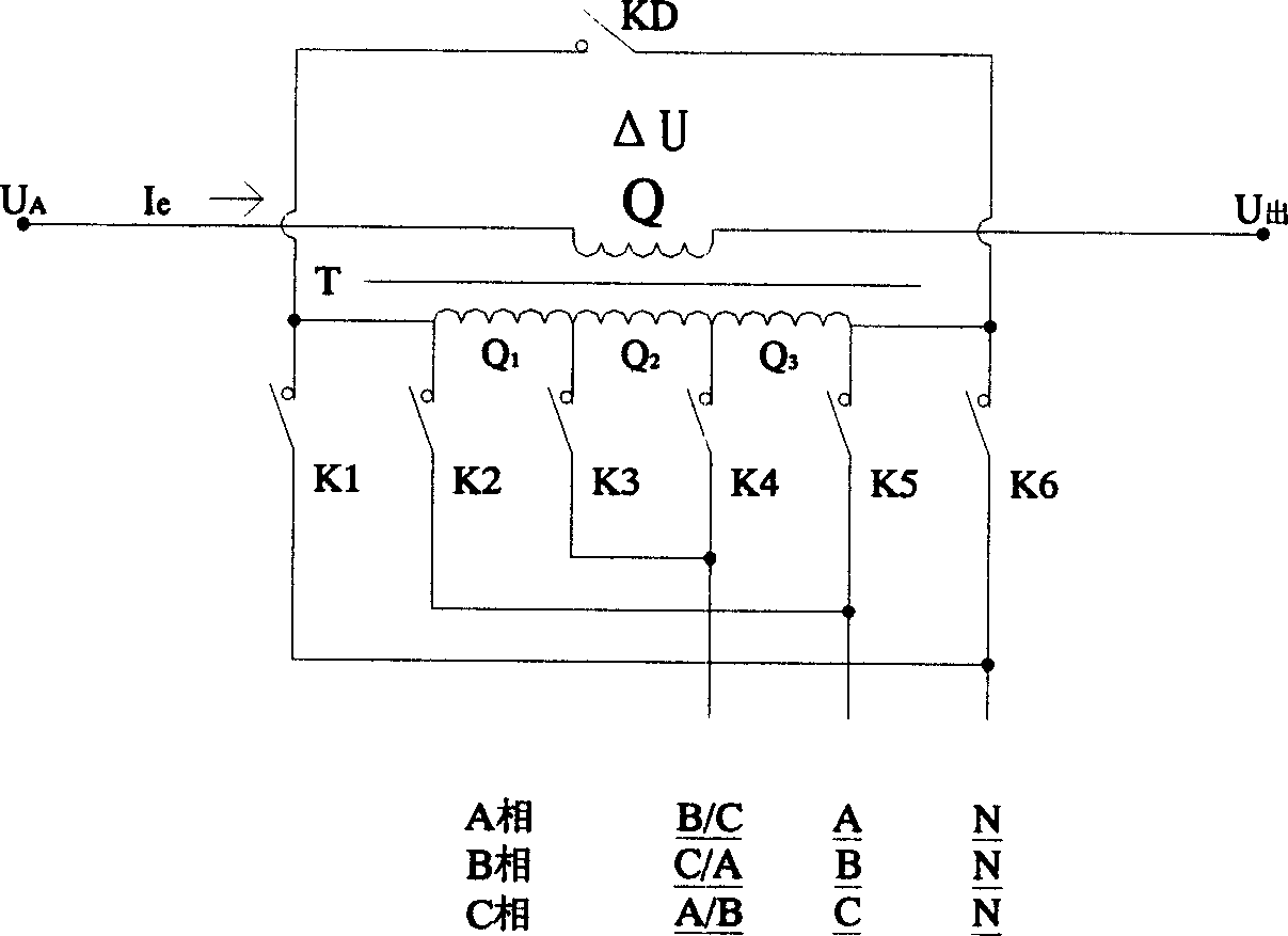

Image

  • Three phase voltage-stabilizing controller and its control method
  • Three phase voltage-stabilizing controller and its control method
  • Three phase voltage-stabilizing controller and its control method

Examples


Embodiment Construction

[0019] Below, the present invention will be described in detail in conjunction with the accompanying drawings.

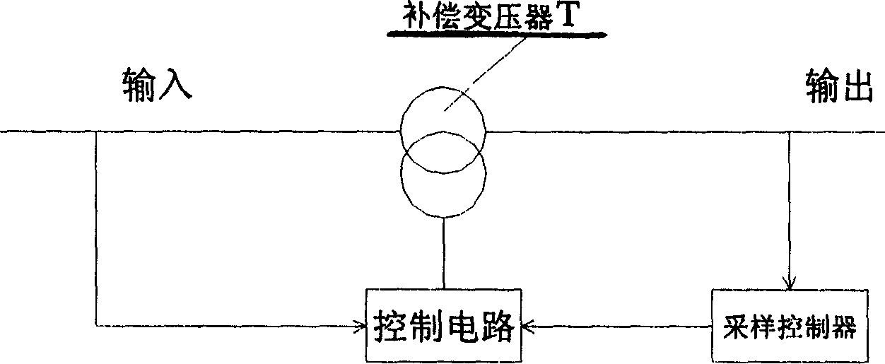
[0020] figure 1 It is a schematic block diagram of the structural principle of the present invention, which is composed of a compensation transformer T, a sampling controller, and a control circuit. Wherein, the compensation winding of the compensation transformer T is a secondary winding, its input terminal is connected to the power supply, and its output terminal is connected to the load. The input end of the sampling controller is connected to the output end of the compensation winding, and the sampling controller includes a computer analysis system, which is responsible for signal acquisition and processing, sending out control instructions, and the control circuit executes the control instructions. The function of the sampling controller can be realized by existing technology. The control circuit is mainly composed of several contactors or solid state relays....


PUM


Abstract

This invention relates to three phase stabilizing regulator comprising microcomputer sampling controller, control circuit and three phase compensation transformer. The characters are: secondary winding of each phase of the transformer having only one coil, and series connected between power source and load; each primary winding having more than one coils and taps, each tap being connected to corresponding phase and zero line of input three phase power source by corresponding contactor of control circuit or contact of solid relay. The main control point is that: phase voltage and / or line voltage in regular or irregular order combination is imposed upon each coil of primary winding of compensationt ransformer, to achieve even compensation, lowering working current in primary winding of compensation transformer. Advantaegs are: simple structure, low cost, high stability precision.

Description

technical field [0001] The invention relates to a circuit device for compensating reactive power, in particular to a voltage stabilizing and regulating device and control method for phase voltage and line voltage of a three-phase circuit. Background technique: [0002] The voltage fluctuation of the existing power grid often exceeds the national regulations during the peak period and the low peak period, even exceeding ±10%, especially the terminal voltage of the low voltage 380V is particularly unstable. The current voltage regulating and stabilizing devices are mainly servo-type voltage regulating methods, and the servo motor type uses carbon brushes for voltage regulation, and the phenomenon of arcing when the carbon brush replaces the thread end slot is easy to burn out the coil and has a high failure rate. It is not suitable for use in relatively harsh environments, which will reduce the operating performance and service life of electrical equipment, and even cause some...

Claims


Application Information

Patent Timeline
IPC IPC(8): H02J3/18
CPCY02E40/30
Inventor 骆武宁
Owner NANNING OUDING ELECTRIC
Why Eureka
Eureka Blog
Learn More