

Drawing heat box device
A hot box and drafting technology, applied in the direction of stretch spinning, etc., can solve problems such as the influence of the heater radiated hot air temperature, and achieve the effect of improving the accuracy of air temperature control, fiber quality and air speed.
- Summary
- Abstract
- Description
- Claims
- Application Information
AI Technical Summary
Problems solved by technology
Method used
Image

Examples
Embodiment Construction
[0031] The present invention will be described in detail below in conjunction with the accompanying drawings and embodiments. This embodiment is only used to explain the present invention, but the protection scope of the claims of the invention is not limited by this embodiment.
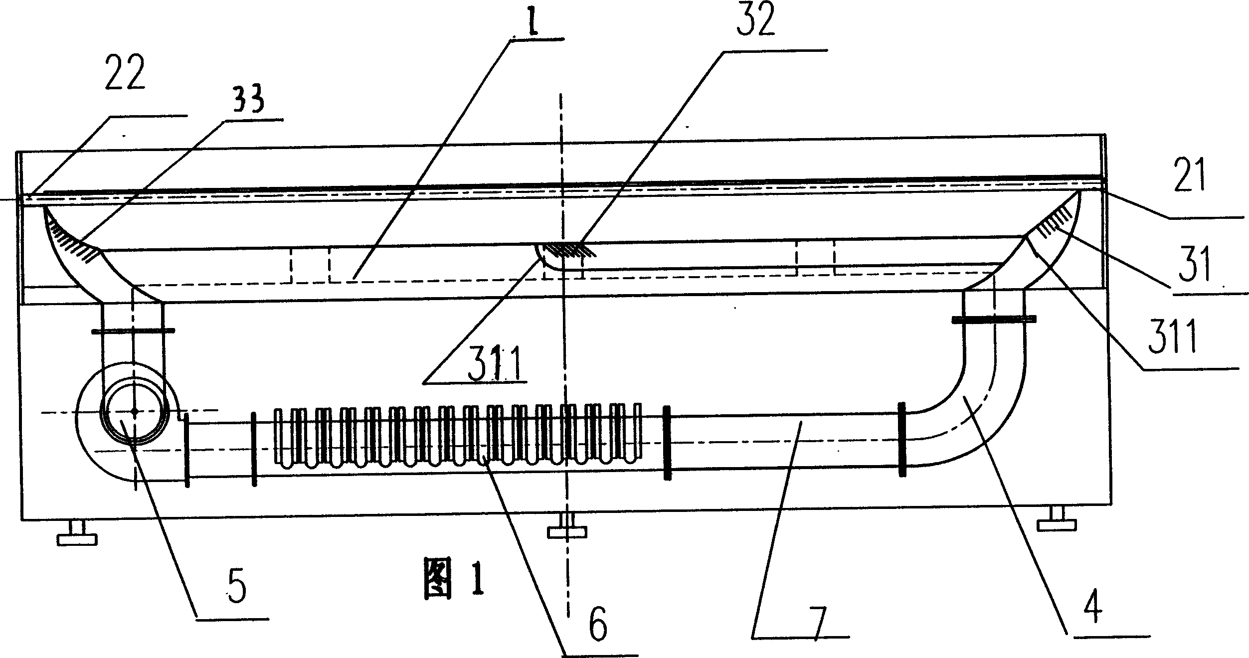
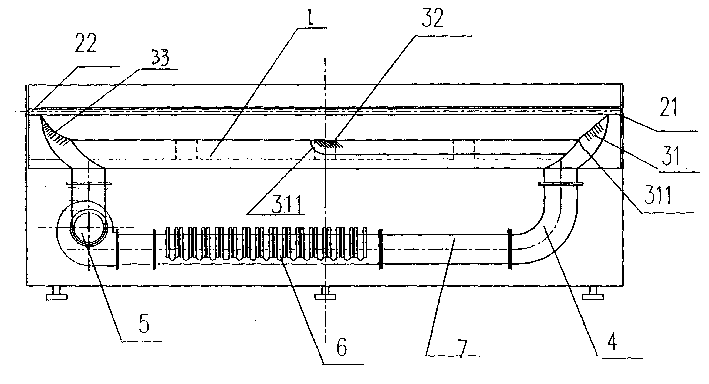
[0032] Fig. 1 shows an embodiment of the drafting hot box device of the present invention, the drafting hot box device in the present embodiment comprises tunnel 1, the tow entrance 21 and the tow outlet 22 that are positioned at the two ends of the tunnel, and are respectively located at the tunnel Two air inlets 31, 32 at one end and the middle position, the wind speed regulating baffle 311 at the two air inlets, the air duct 4 located below the tunnel, the centrifugal fan 5 located at one end of the air duct, the electric heater 6 located in the air duct, and The static pressure box 7 etc. that is positioned at the air duct is composed. In this embodiment, there are two air inlets of the drafting ...
PUM
 Abstract
Description
Claims
Application Information