
Jp2005081297

A technology for cleaning the surface of devices and substrates, which is applied in the directions of identification devices, transportation and packaging, cleaning of flexible items, etc. It can solve the problems of long production time and large-scale production, and achieve the effect of shortening production time.

Inactive Publication Date: 2005-03-16
YODOGAWA MEDEC
View PDF0 Cites 24 Cited by
  • Summary
  • Abstract
  • Description
  • Claims
  • Application Information

AI Technical Summary

Problems solved by technology

However, the structure adopted by the existing grinding device is to move the grinding blade on the surface of the glass substrate while rotating in the state of fixing the glass substrate, so there is a flow time for processing the substrate (the glass substrate is sent into the The total time from inside the device to carrying out the prescribed treatment until the glass substrate is sent out of the device) is long
In addition, in the liquid crystal panel, since the glass substrate is arranged on both sides, in the structure of the above-mentioned existing grinding device, after the processing on one side is completed, the glass substrate is turned over, and then the processing on the other side is performed, so the flow time is shorter. In addition, there is a problem that the footprint of the device (the total installation area projected from directly above when the device is installed on a flat surface) is enlarged
[0004] In addition, in recent years, as the size of the liquid crystal panel has increased, the size of the polishing device has been increased correspondingly, so the problem of increasing the length of the assembly line and increasing the size of the footprint of the device (foot print) has become prominent.

Method used


Image

  • Jp2005081297
  • Jp2005081297
  • Jp2005081297

Examples


Embodiment approach 1

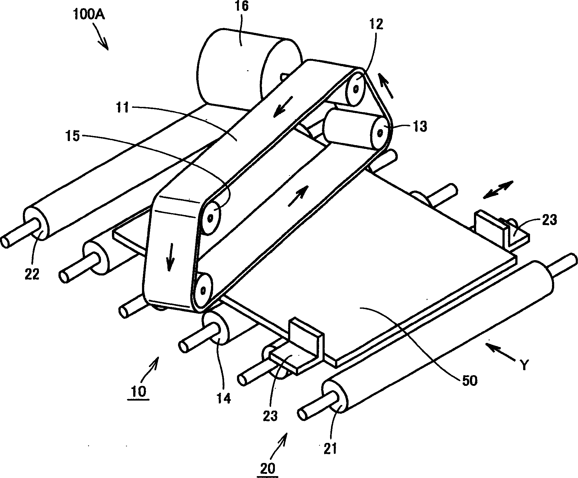
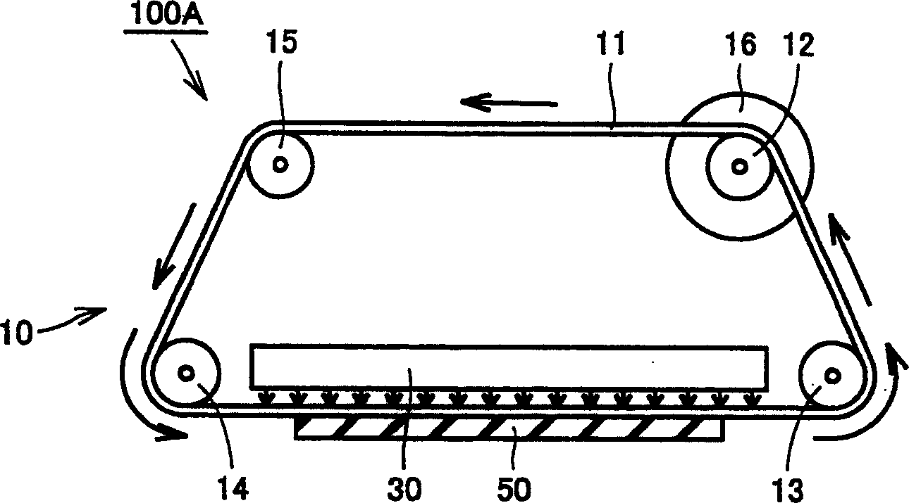
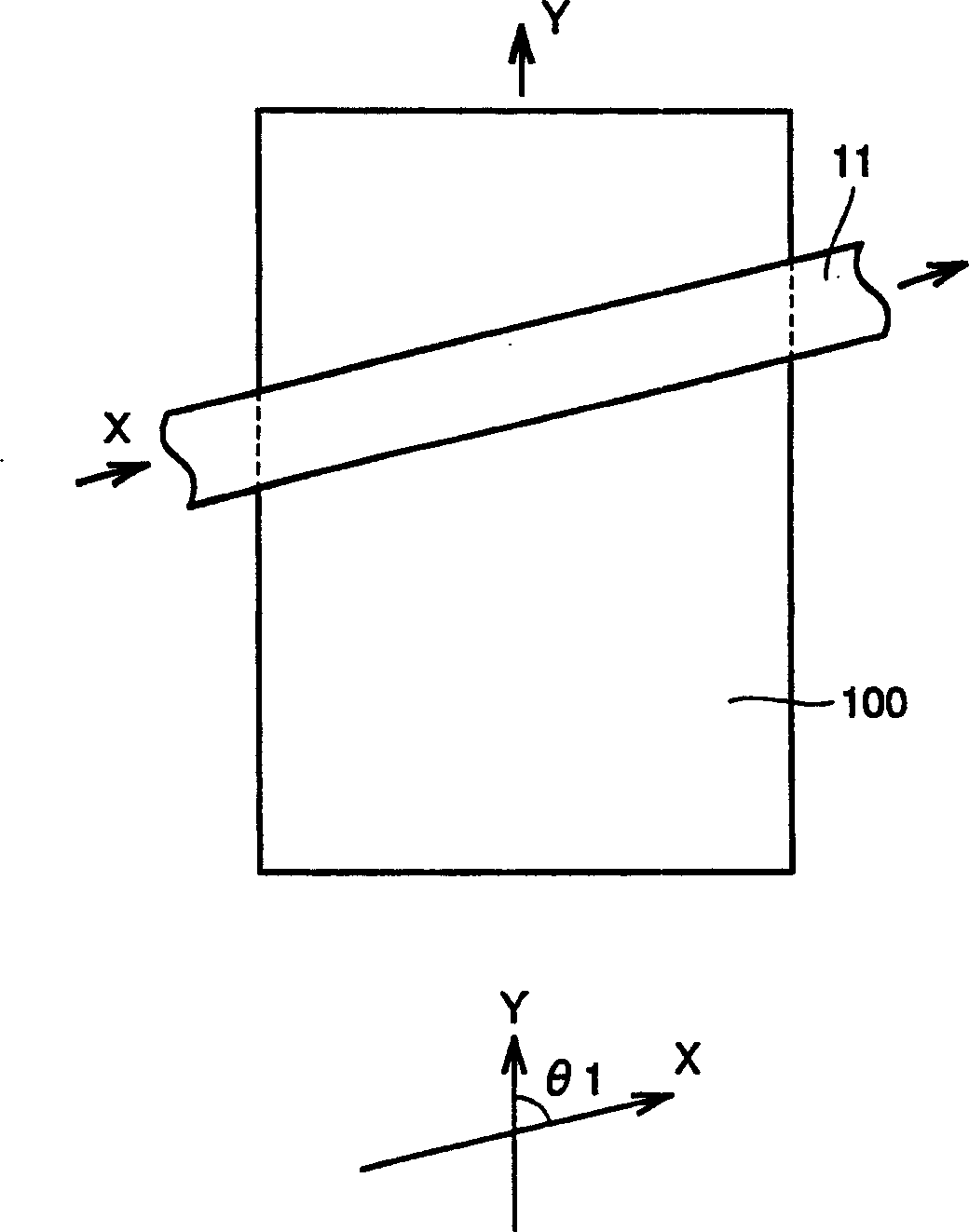
[0022] Below, refer to Figure 1~3 A substrate surface cleaning device according to an embodiment of the present invention will be described. In addition, in this embodiment, as an example, a case where the present invention is applied to a substrate surface cleaning device for performing a cleaning step in the manufacturing process of a liquid crystal panel will be described. Before the pasting process, clean the surface of the glass substrate that constitutes the liquid crystal panel. It should be noted that, figure 1 It is a schematic perspective view showing the basic configuration (schematic) of 100A of substrate support transfer apparatuses according to this embodiment, figure 2 It is a schematic front view showing the basic configuration (schematic) of 100A of substrate support transfer apparatuses according to this embodiment, image 3 It is a schematic plan view showing the relationship between the liquid crystal panel conveyance direction and the cleaning belt sl...

Embodiment

[0029] Next, refer to Figure 4 and Figure 5 The structure of the above-mentioned substrate surface cleaning apparatus 1000 as a specific example of the structure provided with the above-mentioned substrate surface cleaning apparatus 100A will be described. also, Figure 4 is a front view of the substrate surface cleaning device 1000, Figure 5 It is a plan view of the substrate surface cleaning device 1000 .

[0030] refer to Figure 4 and Figure 5 This substrate surface cleaning apparatus 1000 has a main body frame 1001 and side frames 1002 disposed above the main body frame 1001 and facing each other with a predetermined interval therebetween. A substrate cleaning device 1010 and a substrate supporting transfer device 1020 are provided between the side frames 1002 .

[0031]As the substrate supporting transport device 1020, a plurality of input rotary rollers 1021 and output rotary rollers 1022 are arranged side by side. A pulley 1040 for transmitting the rotation ...

Embodiment approach 2

[0041] In the substrate surface cleaning apparatus 100A according to Embodiment 1 described above, a case where one set of substrate cleaning apparatuses 10 are installed above the center portion of the substrate supporting transport apparatus 20 has been described. Therefore, in order to clean both sides of the liquid crystal panel 50, after one side is treated, the liquid crystal panel must be turned over and then the other side is cleaned. Therefore, in the substrate surface cleaning device of this embodiment, a configuration is adopted in which two sets of substrate cleaning devices are installed with the substrates to be transported sandwiched between them. As for the device, the second substrate cleaning device is placed under the substantially central part of the substrate support transfer device.

[0042] Below, refer to Image 6 and Figure 7 , the configuration of the substrate surface cleaning apparatus 100B of this embodiment will be described. and also, Image...


PUM


Abstract

The invention relates to a kind of plaque surface cleaning device, which can shorten time for pipeline process though used for big plaque, and have few spoors on it. The invention consists of device for bracing and carrying the plaque, and device for cleaning the plaque. The former includes many rollers, which are below the liquid crystal panel and supports it, sending the panel in and out in Y direction. The latter includes track cleaning-band that is fixed above center of the supporting and carrying device, drive gear and driven gear that both enwind the cleaning band and give it set force, and drive motor which connects the drive gear and turns the cleaning band to clean. The cleaning band moves on the glass board that used for the liquid crystal panel. The direction in which the cleaning band moves crosses that in which the liquid crystal panel is carried.

Description

technical field [0001] The present invention relates to a substrate surface cleaning device, in particular to a substrate surface cleaning device for removing foreign matter etc. adhering to the substrate surface. Background technique [0002] Conventionally, in the manufacturing process of liquid crystal panels, in order to remove the sealant (UV curable resin, etc.) adhering to the surface of the glass substrate in the process before attaching the polarizing plate, a glass substrate grinding process using a grinder was performed. However, in the manufacturing process of liquid crystal panels in recent years, instead of injecting liquid crystals from the back, a sealing member is placed in advance to cover the entire periphery of the glass substrate, and the liquid crystals are injected dropwise before closing the glass substrates. Therefore, the step of sealing the liquid crystal injection port with a sealant is unnecessary. Therefore, it is not necessary to perform a sub...

Claims


Application Information

Patent Timeline
IPC IPC(8): B08B1/02B08B1/04B08B11/00G02F1/13G09F9/00
CPCB08B3/02B08B3/022B65G49/067G02F1/1303G02F1/1316
Inventor 木村滋
Owner YODOGAWA MEDEC
Features
  • Generate Ideas
  • Intellectual Property
  • Life Sciences
  • Materials
  • Tech Scout
  • Unparalleled Data Quality
  • Higher Quality Content
  • 60% Fewer Hallucinations
Learn More