Rolling machine

A technology for rolling mills and rolling materials, applied in the field of rolling mills, can solve problems such as shortening sticking molds, lowering productivity, and not being rolled

Inactive Publication Date: 2005-03-16
KOBE STEEL LTD
View PDF0 Cites 10 Cited by
  • Summary
  • Abstract
  • Description
  • Claims
  • Application Information

AI Technical Summary

Problems solved by technology

[0003] The above-mentioned prior art has been pointed out to have the following problem: because the roll gap is opened when the rolled material is passed on the work roll (roll), therefore, the front end of the rolled material is still not rolled, and the front end becomes waste.
[0009] However, on the contrary, the pad part is made of soft material, and the wear of the pad is serious. Therefore, it must be replaced after several rolls are rolled (several times in one shift), and time is lost due to the preparation and replacement of the pad parts. Reduced productivity
[0010] When rolling the front end, the upper die is lowered, the lower die is raised, and the front end of the rolled material is clamped by the upper and lower clamps, the die is advanced, and the front end of the roll

Method used


Image

  • Rolling machine
  • Rolling machine
  • Rolling machine

Examples


Embodiment Construction

[0028] Hereinafter, preferred embodiments of the present invention will be described with reference to the drawings.

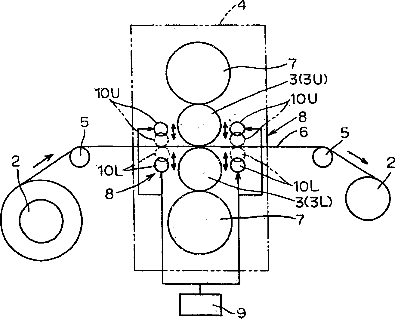
[0029] In this embodiment, a reversing cold rolling mill 1 is shown as an example of the rolling mill 1 . like figure 1 As shown, the configuration of the rolling mill 1 is that a rolling mill stand 4 is arranged between a pair of coilers 2 spaced apart from a predetermined interval, and the rolling mill stand 4 is equipped with a pair of upper and lower work rolls (rolls) 3 (3U, 3L). ).

[0030] One deflector roll 5 is disposed between each coiler 2 and the rolling stand 4 . The rolled material 6 (strip) is wound on a coiler 2, and when the rolling mill 6 reciprocates between each coiler 2, it is guided between each coiler 2 and the rolling stand 4 by the above-mentioned deflectors. Roller 5 is supported.

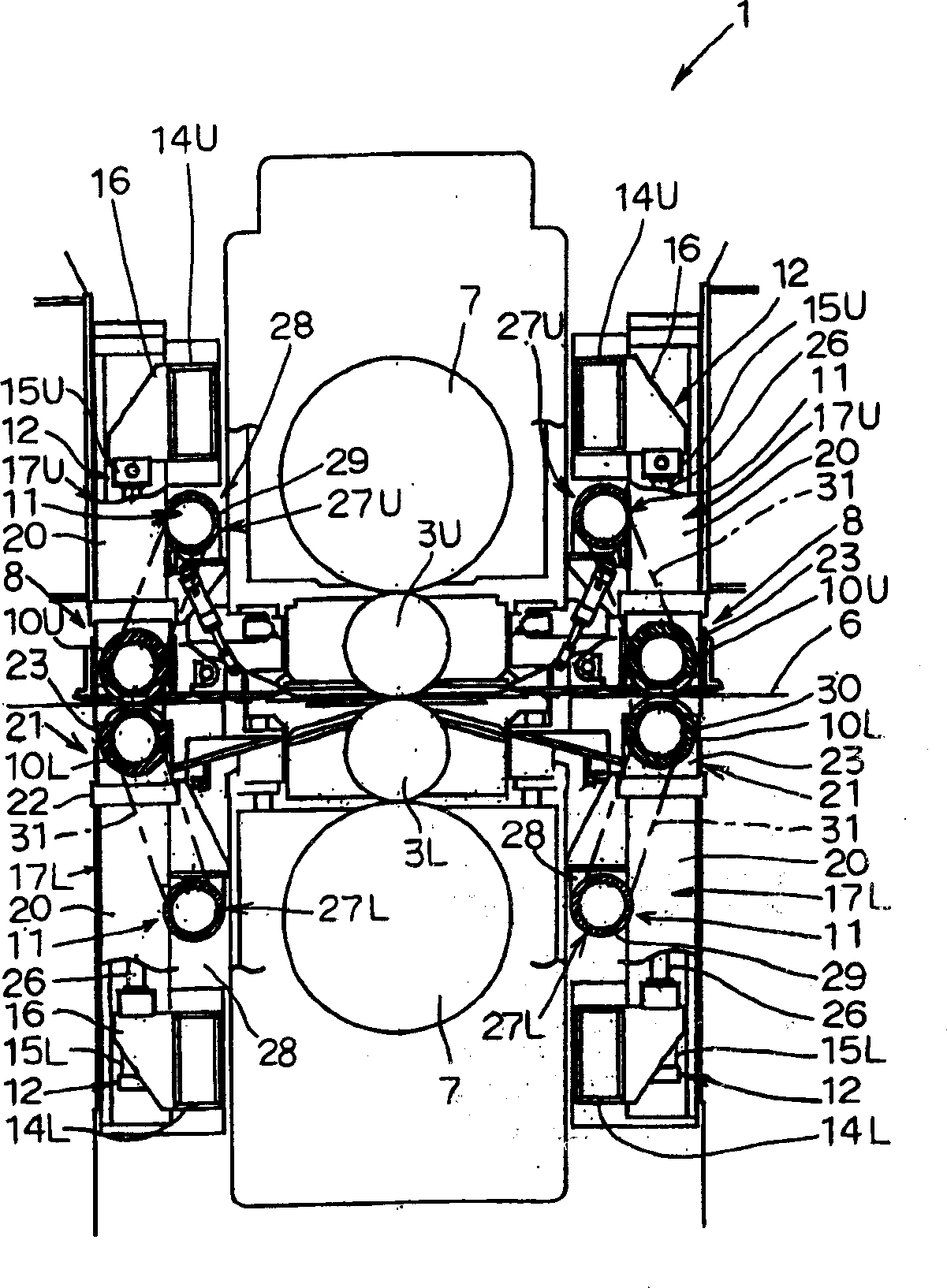
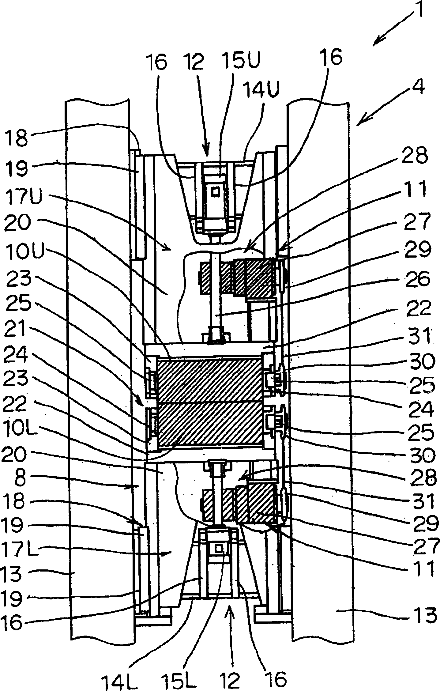
[0031] The upper and lower pair of work rolls 3 are freely rotated in forward and reverse directions by a drive motor. In addition, each work roll 3 ...


PUM


Abstract

The invention fixes a pair of carrying roller on the intake of the rolling machine to lead the mill bar between another pair of roller which is respectively up and down the machine also. With such a device, front of the mill bar can be rolled leaving few disfigurements though using no film on it.

Description

technical field [0001] The present invention relates to a rolling mill capable of appropriately rolling the ends of a rolled material. Background technique [0002] For a long time, as this kind of rolling mill, there is a rolling mill set in the following way: (1) when the rolling material is passed on the work roll, the roll gap is opened first so as not to hinder the passing of the plate (through the plate), (2) the rolling After the material passes through the rolling mill, the roll gap becomes a specified value through a hydraulic pressing device, (3) the rolled material is coiled on the coiler on the exit side, (4) rolled, and (5) the rear end of the rolled material is rolled When leaving the coiler on the entrance side, a certain tension is applied to the rear end side portion of the rolled material with a tension applying device (refer to JP-A-10.263613). [0003] In the prior art described above, it has been pointed out that there is a problem that the front end of...

Claims


Application Information

Patent Timeline
IPC IPC(8): B21B39/08B21B1/22B21B1/36B21B13/02B21B39/02B21B39/06B21B39/10
CPCB21B39/006B21B39/02B21B39/06B21B39/10B21B2275/02B21B2275/04B21B2275/05
Inventor 上杉宪一井上哲雄本池澄夫
Owner KOBE STEEL LTD
Why Eureka
Try Eureka