
Device and method for discharging drainage sand by utilizing electromagnetism

A technology of drainage sand and electromagnetism, which is used in casting melt containers, mechanical cleaning, manufacturing tools, etc., can solve the problems of difficult installation and incomplete removal process, and achieve the effect of high return, low investment and improved purity.

Inactive Publication Date: 2020-05-26
BAOSHAN IRON & STEEL CO LTD
View PDF9 Cites 1 Cited by
  • Summary
  • Abstract
  • Description
  • Claims
  • Application Information

AI Technical Summary

Problems solved by technology

When using this device to remove drainage sand, additional devices and operations are added, and it is also difficult to install these devices under certain working conditions
[0007] Although the above-mentioned patents have proposed solutions for the removal of drainage sand from several aspects, generally speaking, some of these solutions have introduced additional new substances, and some have added larger equipment structures to remove the sand from the molten steel. As far as the drainage sand is concerned, there is no proposed plan, so the removal process is not thorough

Method used


Image

  • Device and method for discharging drainage sand by utilizing electromagnetism
  • Device and method for discharging drainage sand by utilizing electromagnetism

Examples


Embodiment 1

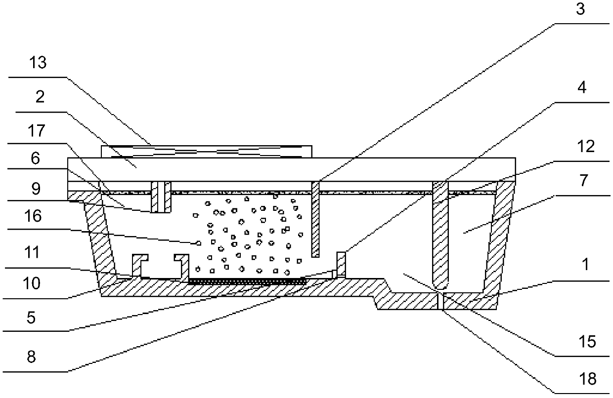
[0053] The tundish is a 25t channel-type single-flow tundish, which is divided into a steel chamber and a pouring chamber. The two chambers are connected through two channels. The thickness of the metal baffle is 2mm. When pouring, the metal baffle is placed in the channel. At the entrance, after pouring is started, the drainage sand falls into the tundish steel chamber before the molten steel, and then is driven by the molten steel to move in the tundish steel chamber. When the liquid level reaches the channel, the molten steel is blocked by the metal baffle. Can not quickly enter the channel, at this time, the liquid level of molten steel rises rapidly, submerging the position of the channel. As the molten steel increases, the metal baffle melts, and the molten steel enters the channel and flows into the pouring chamber. When the liquid level in the steel chamber rises above 200mm, open the air blowing device at the bottom of the tundish, and set the air volume to 0.2L / min. ...

Embodiment 2

[0056] The tundish is a 32t channel-type single-flow tundish, which is divided into a steel chamber and a pouring chamber. The two chambers are connected through two channels. The thickness of the metal baffle is 3mm. When pouring, the metal baffle is placed in the channel. At the entrance, after pouring is started, the drainage sand falls into the tundish steel chamber before the molten steel, and then is driven by the molten steel to move in the tundish steel chamber. When the liquid level reaches the channel, the molten steel is blocked by the metal baffle. Can not quickly enter the channel, at this time, the liquid level of molten steel rises rapidly, submerging the position of the channel. As the molten steel increases, the metal baffle melts, and the molten steel enters the channel and flows into the pouring chamber. When the liquid level in the steel chamber rises above 200mm, open the air blowing device at the bottom of the tundish, and set the air volume to 0.5L / min. ...


PUM

PropertyMeasurementUnit
thicknessaaaaaaaaaa
thicknessaaaaaaaaaa
thicknessaaaaaaaaaa

Abstract

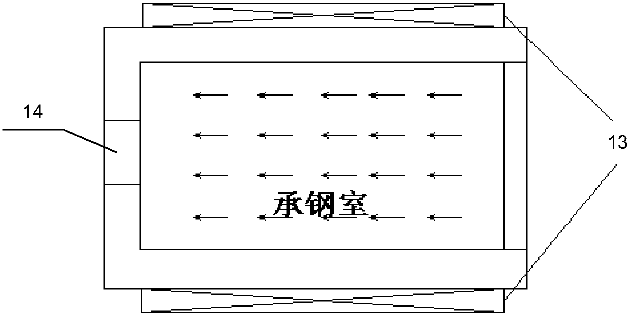
The invention discloses a device and a method for discharging drainage sand by utilizing electromagnetism. The device comprises a tundish, wherein a ladle cover is arranged at the top end of the tundish, a slag blocking dam, a slag blocking weir and a metal baffle are arranged in the tundish, the interior of the tundish is divided into a steel bearing chamber and a steel pouring chamber, a steel through hole is formed in the slag blocking weir, and the metal baffle is connected with the steel through steel hole; the steel bearing chamber is provided with a long water port, a turbulence suppressor and a bottom blowing device, the long water port is arranged above the steel bearing chamber, the turbulence suppressor and the bottom blowing device are both arranged at the bottom of the steel bearing chamber, and the turbulence suppressor is arranged below the long water port; the steel pouring chamber is provided with a water outlet and a stopper rod, the stopper rod is arranged above thesteel pouring chamber, and the water outlet is arranged at the bottom of the steel pouring chamber and correspondingly arranged below the stopper rod; and the tundish is further provided with a traveling wave electromagnetic induction device, and the traveling wave electromagnetic induction device is connected on the tundish cover or on two sides of the tundish wall. The device and method disclosed by the invention can effectively discharge the drainage sand entered into the tundish, thereby reducing the pollution of the drainage sand to the molten steel, and improving the cleanliness of the molten steel.

Description

technical field [0001] The invention relates to the technical field of continuous casting, and more specifically relates to a device for discharging drainage sand by using electromagnetic force and a method for discharging drainage sand. Background technique [0002] Drainage sand is used for blocking and drainage at the injection hole at the bottom of the ladle. It is an essential refractory material for the ladle. Before the ladle is ready to inject molten steel, first use drainage sand to block the injection hole, and then pour molten steel. For the use of drainage sand, the existing drainage sand generally has better high-temperature sintering performance, that is, it can quickly form a sintered shell that can prevent the molten steel from flowing out after being in contact with molten steel. The drainage sand in the lower part plays more of a certain fluidity. When the ladle is pouring, the sliding plate is opened, and the drainage sand installed in the nozzle can auto...

Claims


Application Information

Patent Timeline
Patent Type & Authority Applications(China)
IPC IPC(8): B22D41/44B22D43/00
CPCB22D41/44B22D43/002
Inventor 任三兵樊俊飞方园
Owner BAOSHAN IRON & STEEL CO LTD
Learn More