Steel plate-concrete flitch plate

A technology of concrete and composite slabs, applied in bridge parts, building materials, bridges, etc., can solve the problems of difficult and effective realization of design and construction, and achieve the effects of being conducive to controlling concrete cracking, having good environmental effects and reducing the self-weight of the structure.

Inactive Publication Date: 2005-03-16
TSINGHUA UNIV
View PDF0 Cites 13 Cited by
  • Summary
  • Abstract
  • Description
  • Claims
  • Application Information

AI Technical Summary

Problems solved by technology

The maximum principal tensile stress direction of the slab bottom of an integral cast-in-place slab bridge varies with various factors such as bridge width and inclination. Therefore, for its reinforc

Method used


Image

  • Steel plate-concrete flitch plate
  • Steel plate-concrete flitch plate
  • Steel plate-concrete flitch plate

Examples


Embodiment Construction

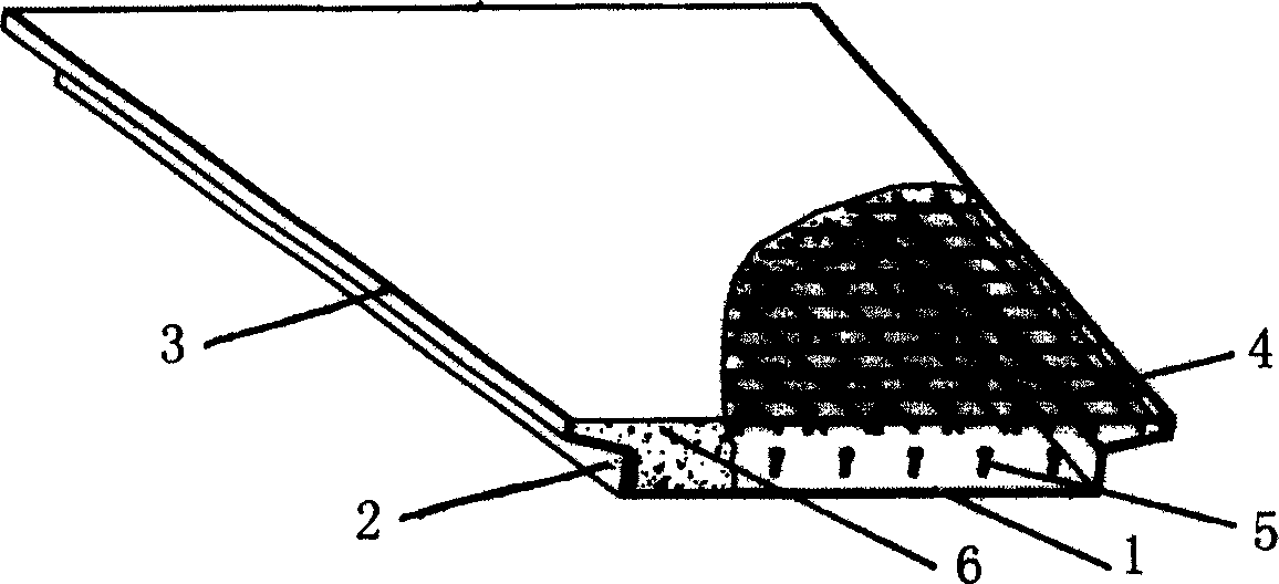
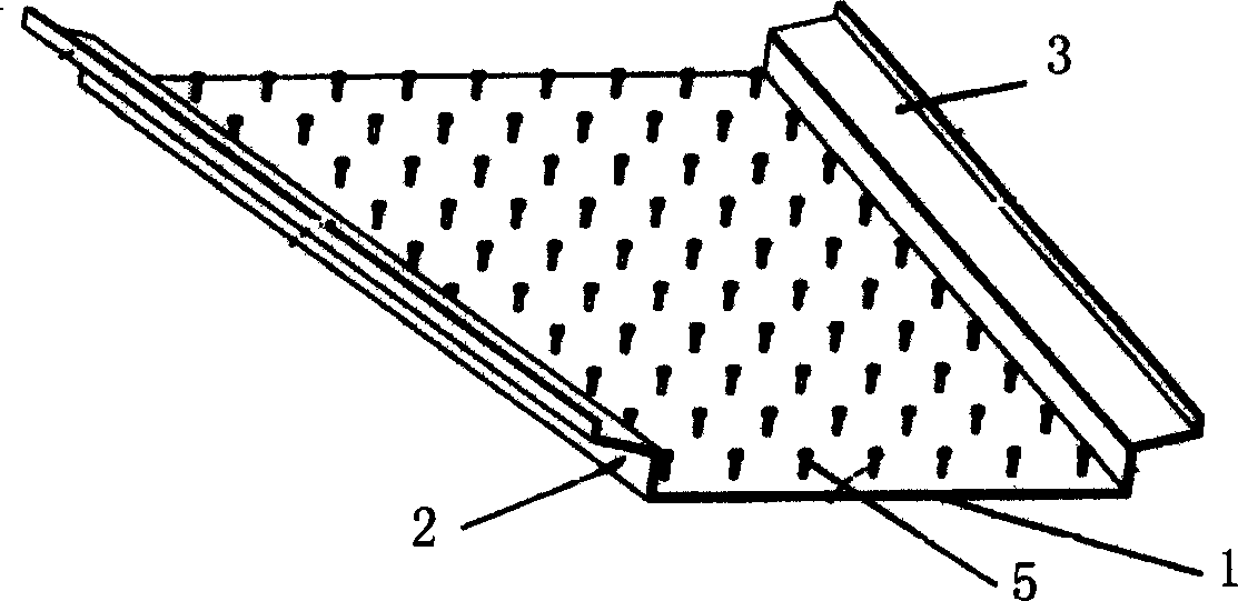
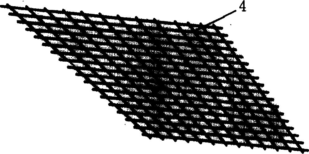
[0014] The invention provides a steel plate-concrete composite plate which can significantly improve its bearing capacity, rigidity and crack resistance. exist figure 1 , figure 2 and image 3 In the schematic diagram of the steel plate-concrete composite plate structure shown, the shear connector stud 5 is welded on the prefabricated steel plate 1, the steel mesh 4 is set on the upper part of the stud 5, and the concrete 6 is poured on both sides of the steel plate 1 to block Between the plates 2, the pegs 5 and the steel mesh 4 are wrapped, and are combined with the steel plate 1, and the surface is flush with the upper edge of the upper wing plate 3 of the steel plate 1.

[0015] The specific embodiments of the present invention will be further described below in conjunction with the accompanying drawings.

[0016] Construction process of the present invention is:

[0017] The steel plate-concrete composite plate structure of the present invention is composed of two pa...


PUM


Abstract

The invention discloses a steel plate-concrete flitch plate which can improve the structure bearing ability, hardness and crack resistance, belonging to bridge element area. The process is that: welding pin cutting resistant connection on the pre-moulding steel plate, setting steel net on the upper of the pin, casting concrete to assemble into an integrated unit. The process fully displays the compression-resistant performance of the concrete. The steel plate resist to bottom plate stretch-draw force from different direction. The pin delivers the shear between the steel plate and concrete and prevents the vertical separation therebetween. The invention solves the uncontrollable concrete crack problem in the application process of the steel reinforced concrete inclined, bend bridge. The inveniton tends to satisfy the plane figure of the bridge and is suitable for burden special-shaped plate in the inclined and bend bridge with a medium and small spin and building structure.

Description

technical field [0001] The invention belongs to the scope of bridge components, in particular to a steel plate-concrete composite plate capable of significantly improving its bearing capacity, rigidity and crack resistance. Background technique [0002] Slanted bridges and curved bridges occupy a large proportion of high-grade highway bridges. When the span of oblique and curved bridges is small, an integral cast-in-place reinforced concrete slab bridge is often used. The most common damage of this type of structure is the cracking of the concrete floor, among which the cracks in the longitudinal direction of the floor at an acute angle are the most representative. Cracks will seriously reduce the bearing capacity, stiffness and durability of the structure. The maximum principal tensile stress direction of the slab bottom of an integral cast-in-place slab bridge varies with various factors such as bridge width and inclination. Therefore, for its reinforcement design, it is...

Claims


Application Information

Patent Timeline
IPC IPC(8): E01D19/00E04C2/26
Inventor 聂建国
Owner TSINGHUA UNIV
Why Eureka
Try Eureka