Electric vacuum cleaner

A vacuum cleaner and electric technology, used in vacuum cleaners, household appliances, cleaning equipment, etc., can solve the problems of metal plate obstruction, shortened battery life, temperature imbalance, etc., and achieve the effect of prolonging life and improving usability.

Inactive Publication Date: 2005-03-23
PANASONIC CORP
View PDF1 Cites 15 Cited by
  • Summary
  • Abstract
  • Description
  • Claims
  • Application Information

AI Technical Summary

Problems solved by technology

[0006] However, if the above-mentioned structure is adopted, after the secondary battery is cooled, the exhaust gas will be directly discharged into the atmosphere from the secondary battery compartment through the exhaust port, causing the temperature of the exhaust gas discharged into the atmosphere to be too high, making the use of the vacuum cleaner difficult. performance drop
[0007] In addition, with the above configuration, only the batteries that are directly blown by the exhaust air flow during discharge are cooled, resulting in uneven temperature among the indivi

Method used


Image

  • Electric vacuum cleaner
  • Electric vacuum cleaner
  • Electric vacuum cleaner

Examples


Embodiment 1

[0057] First, with the help of Figure 1 to Figure 8 The first embodiment of the present invention will be described.

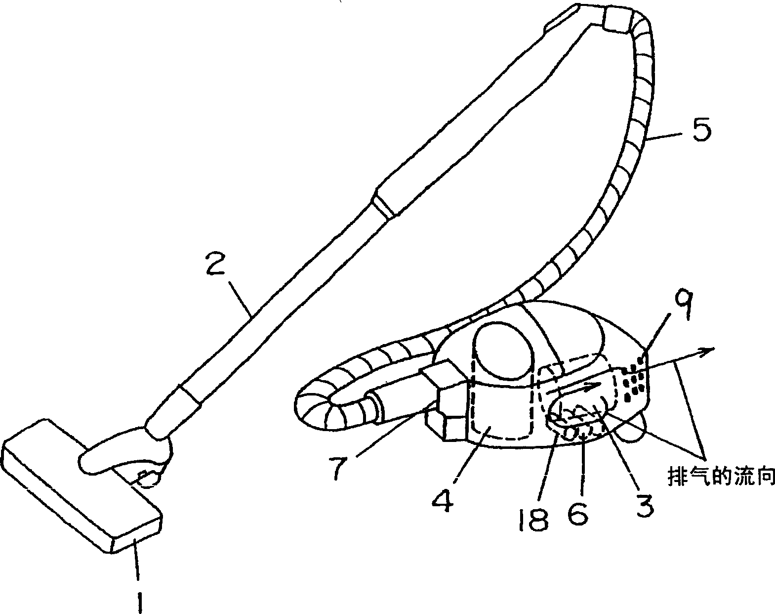
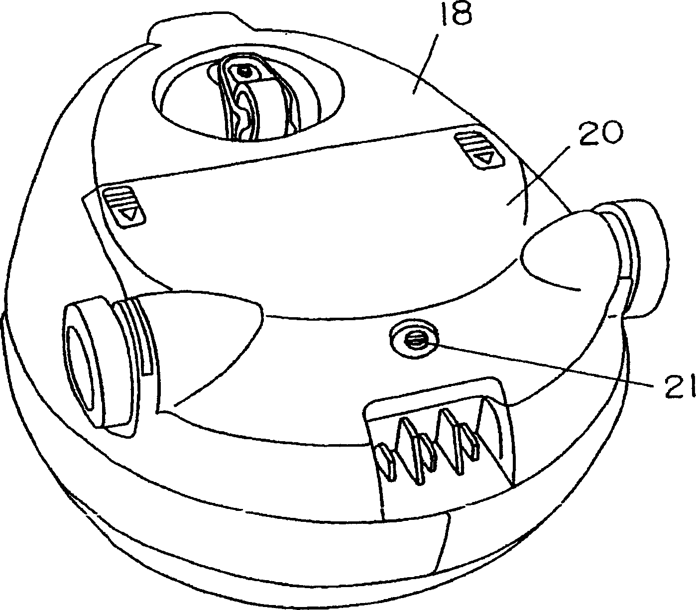
[0058] As shown in the figure, the main body 18 of the vacuum cleaner is provided with: an electric blower chamber 8 which is an electric blower for generating a dust-absorbing airflow inside, that is, an electric blower chamber 8 of the frequency converter motor 3; The battery 6, and the secondary battery compartment 19 in which the secondary battery 6 is arranged below the frequency converter motor 3; In addition, one end of the hose 5 is connected to the upstream side of the dust collecting box 4 in the main body 18 of the vacuum cleaner, and the other end is connected to the floor suction head 1 through the extension pipe 2 .

[0059] When the frequency converter motor 3 is working, it will generate a dust suction airflow, and the dust and the dust suction airflow will be sucked from the ground suction head 1 together. The dust box 4 in the main body 18...

Embodiment 2

[0073] pass below Figure 9 The second embodiment of the present invention will be described. Wherein, the parts that are the same as those in the previous embodiment are given the same symbols, and repeated description thereof will be omitted.

[0074] In this embodiment, an outlet B41 communicating with the electric blower chamber 8 and the secondary battery compartment 19 and a soundproof tube 16 covering the outer periphery of the exhaust side of the inverter motor 3 are provided. Wherein, the discharge port B41 for releasing the exhaust gas of the inverter motor 3 into the secondary battery compartment 19 is provided on the soundproof tube 16 .

[0075] The operation and action of the electric vacuum cleaner having the above construction will be described below.

[0076] Due to the formation of a passage for the exhaust gas to forcibly flow into the secondary battery compartment 19 , all the exhaust gas from the inverter motor 3 can be used for cooling the secondary bat...

Embodiment 3

[0078] Use below Figure 10 ~ Figure 15 A third embodiment of the present invention will be described.

[0079] Figure 10 The main body 118 of the vacuum cleaner includes an electric blower 103 for generating dust suction airflow, and its lower part is provided with a power supply for driving the electric blower 103, that is, a secondary battery composed of a plurality of slightly cylindrical secondary batteries 106 bundled together. Group. The dust collecting box 104 is provided on the upstream side of the dust suction air flow of the electric blower 103 . In addition, the upstream side of the dust box 104 in the main body 118 is connected with one end of the hose 105 , and the other end of the hose 105 is connected with the floor suction head 101 through the extension tube 102 . When the electric blower 103 works, it will generate a dust suction airflow, and the dust will be sucked from the floor suction head 101 together with the dust suction airflow. The dust collecti...


PUM


Abstract

The vacuum cleaner has an electric blower chamber 3 having an electric blower 3 built in it for generating suction wind, and a secondary battery storing part 19 having the secondary battery 6 built in it for supplying power source to the electric blower 3. At least a part of exhaust discharged by the electric blower 3 flows into the secondary battery storing part 19, and thereafter it flows back again to the electric blower chamber 8. After cooling the secondary battery 6 by the exhaust, the exhaust does not discharged directly to the atmosphere from the secondary battery storing part 19 but it is returned to the electric blower chamber 8. Thereby, temperature of the exhaust discharged to the atmosphere is low and usability is high, and cooling of the secondary battery 6 can also be performed, so that the vacuum cleaner capable of improving life of the secondary battery is achieved.

Description

technical field [0001] The invention relates to a rechargeable electric vacuum cleaner used in common households. Background technique [0002] Describe the situation of the existing electric vacuum cleaner below. [0003] In the existing rechargeable electric vacuum cleaner, in addition to the electric blower, the inside of the main body of the vacuum cleaner is also provided with: a secondary battery compartment for installing a secondary battery for driving the electric blower; Exhaust air from the electric blower to the outside; and an air flow path that directs air from the electric blower to the exhaust port. The secondary battery compartment is provided in the air flow path, and the secondary battery compartment has an electric blower side wall portion on the electric blower side and an exhaust side wall portion on the exhaust port side. An inflow hole is formed on the side wall of the electric blower to allow air to flow inside, and an outflow hole is formed on the...

Claims


Application Information

Patent Timeline
IPC IPC(8): A47L9/00
Inventor 宫原敏文恩田雅一长冈宏和
Owner PANASONIC CORP
Why Eureka
Try Eureka