Apparatus for measuring ultra narrow laser line width by Brillouin optical fibre ring laser and measuring method

A ring laser and laser line width technology, applied in the direction of optical devices, measuring devices, instruments, etc., can solve the problems of low measurement accuracy and complex devices

Inactive Publication Date: 2005-03-23
HARBIN INST OF TECH
View PDF0 Cites 20 Cited by
  • Summary
  • Abstract
  • Description
  • Claims
  • Application Information

AI Technical Summary

Problems solved by technology

[0003] The purpose of the present invention is to provide a device and method for measuring the ultra-narrow laser line width using a Brillouin fiber ring las...

Method used


Image

  • Apparatus for measuring ultra narrow laser line width by Brillouin optical fibre ring laser and measuring method
  • Apparatus for measuring ultra narrow laser line width by Brillouin optical fibre ring laser and measuring method
  • Apparatus for measuring ultra narrow laser line width by Brillouin optical fibre ring laser and measuring method

Examples


specific Embodiment approach 1

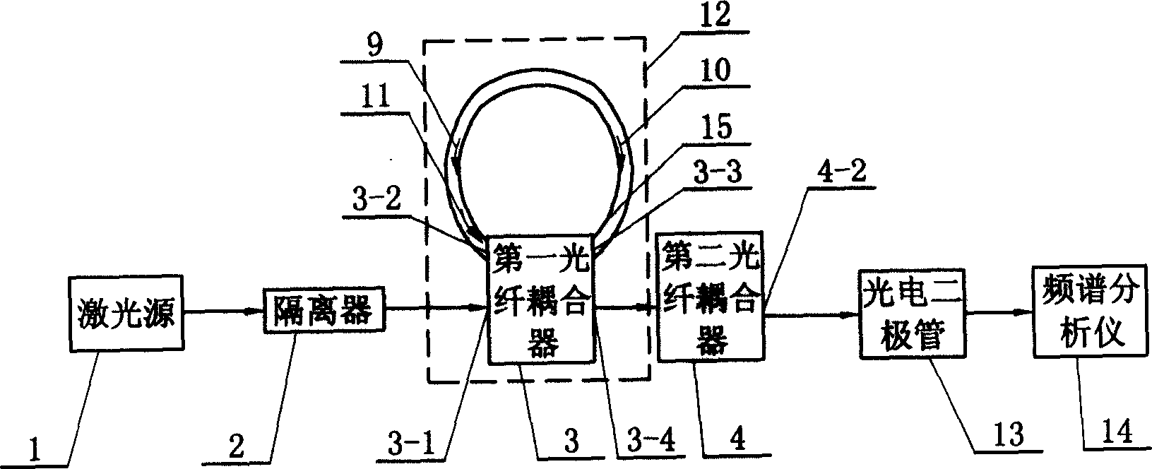
[0005] Specific implementation mode one: this implementation mode refers to figure 1 , which consists of a Brillouin fiber ring laser, a second fiber coupler 4, a photodiode 13, and a spectrum analyzer 14. The Brillouin fiber ring laser consists of a laser source 1, an isolator 2, and a fiber ring cavity 12. Optical fiber ring cavity 12 is made up of single-mode fiber, the first fiber coupler 3, and one end of the split ring 15 that is made of single-mode fiber is connected with the optical transmission port 3-2 of the first fiber coupler 3, and the other end of split ring 15 It is connected with the optical transmission port 3-3 of the first optical fiber coupler 3. The coupling ratio of the first fiber coupler 3 is 95:5˜98:2, and the coupling ratio of the second fiber coupler 4 is 55:45˜45:55. The output end of the laser source 1 is connected to the input end of the isolator 2 by an optical fiber, the output end of the isolator 2 is connected to the input end 3-1 of the fi...

specific Embodiment approach 2

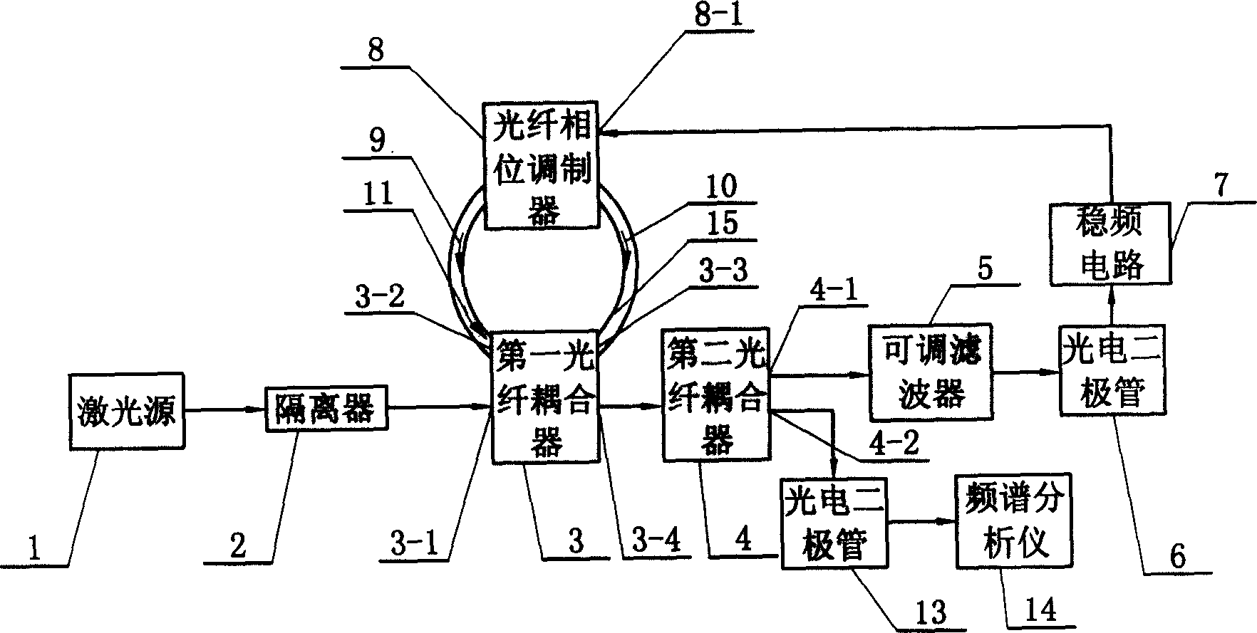
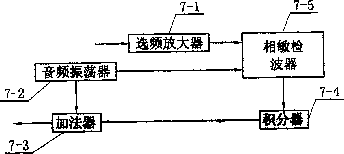
[0006] Specific implementation mode two: refer to figure 2 The difference between this embodiment and the first embodiment is that it also includes a tunable filter 5 , a photodiode 6 , a frequency stabilization circuit 7 , and an optical fiber phase modulator 8 . The second output end 4-1 of the second fiber coupler 4 is connected by an optical fiber with the input end of the tunable filter 5, and the output end of the tunable filter 5 is connected by an optical fiber with the input end of the photodiode 6, and the photodiode 6 The output end of the frequency stabilizing circuit 7 is connected by wires, and the output end of the frequency stabilizing circuit 7 is connected with the voltage input end 8-1 of the optical fiber phase modulator 8 by wires. The two optical transmission ports of the optical fiber phase modulator 8 are connected in series in a split ring 15 composed of a single-mode optical fiber, and are arranged symmetrically with the first optical fiber coupler 3...


PUM


Abstract

The invention is a device and measuring method for using Brillouin optical fiber circle laser to measure linewidth of ultra-narrow laser, which relates to a measuring device and method for laser linewidth. The output of the laser source is connected to the input of the isolator, the output of the isolator is connected to the input of the fiber coupler, the output of the coupler is connected to the inlet of the fiber coupler, the output of the fiber coupler is connected to the input of the photoelectric diode, the output of the photoelectric diode is connected to the input of the frequency spectrum analyzer, the fiber circular cavity is formed by connection one end of the aperture circle made up of unimodular fiber and the port of the fiber coupler, another end of the aperture circle is connected to the port three of the coupler. The method is: the laser needed to be measured is sent into the fiber circle cavity, when the power of the laser needed to be measured reach the threshold of SBS, it generates a first order Stokes light in the coupler, when the power of the first order stokes light reach the SBS threshold, it generates the second order stokes light in the coupler, then the second order stokes light and the laser needed to be measured frequency are analyzed by the frequency spectrum analyzer, and the linewidth can be acquired.

Description

Technical field: [0001] The invention relates to a measuring device and a measuring method for measuring the line width of a laser, in particular to a device and a measuring method for measuring an ultra-narrow laser line width using a Brillouin fiber ring laser. Background technique: [0002] At present, the method used to measure the laser linewidth below 1MHz is the fiber delay self-beating method. This method increases the resolution by increasing the length of the delay fiber. In theory, as long as the delay fiber is long enough, the resolvable frequency can be small enough. But its disadvantage also lies in this. If you want to measure the extremely narrow laser line width, you must use a long enough optical fiber, which makes the measurement device complicated and the measurement accuracy is not high. Invention content: [0003] The purpose of the present invention is to provide a device and method for measuring ultra-narrow laser line width using a Brillouin fiber...

Claims


Application Information

Patent Timeline
IPC IPC(8): G01B11/02
Inventor 吕志伟董永康何伟明吕月兰
Owner HARBIN INST OF TECH
Why Eureka
Try Eureka