Luminous device

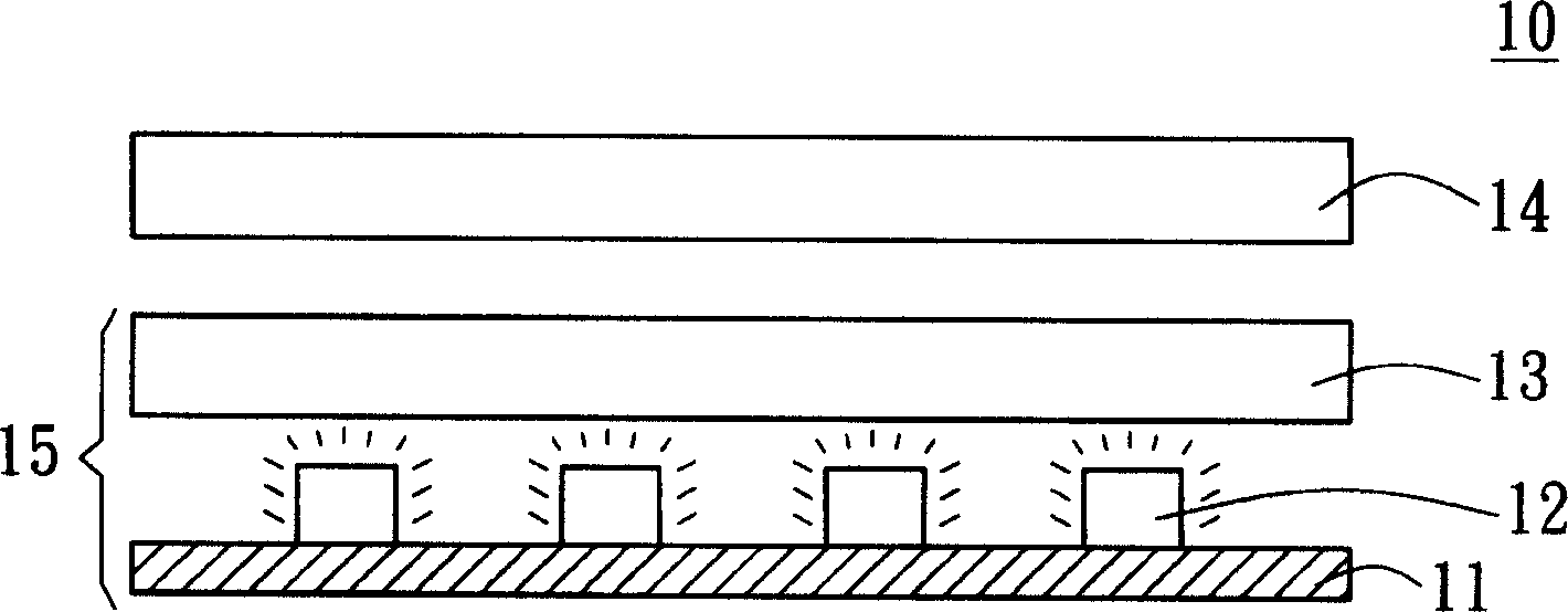
A light-emitting device and light-emitting diode technology, which is applied in the direction of lighting devices, optics, light sources, etc., can solve the problems of affecting the quality of light mixing and the deflection of the diffuser 13

Inactive Publication Date: 2005-03-23
AU OPTRONICS CORP
View PDF0 Cites 9 Cited by
  • Summary
  • Abstract
  • Description
  • Claims
  • Application Information

AI Technical Summary

Problems solved by technology

Since there is no supporting structure between the diffuser 13 and the LEDs 12 to support the di...

Method used


Image

  • Luminous device
  • Luminous device
  • Luminous device

Examples


Embodiment 1

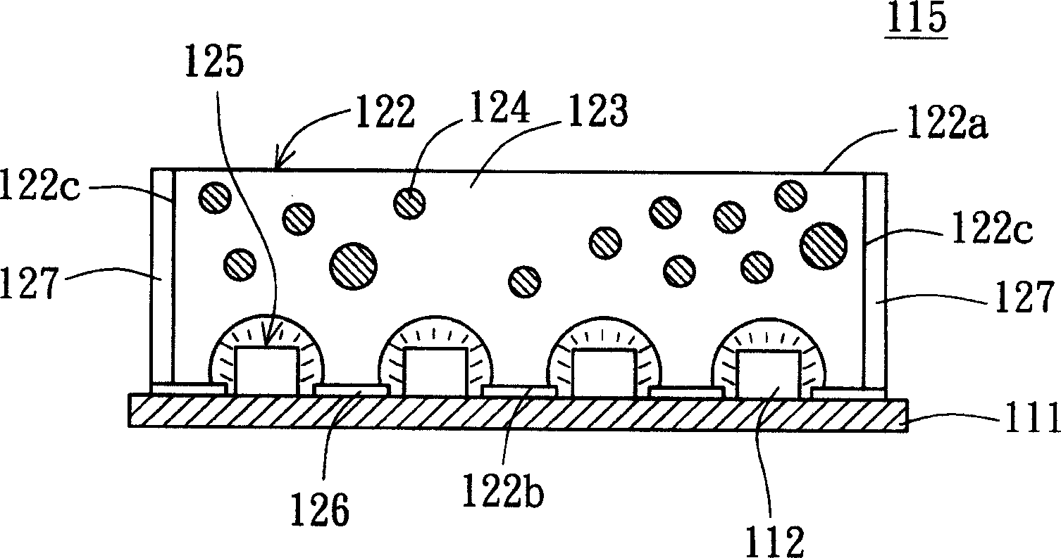
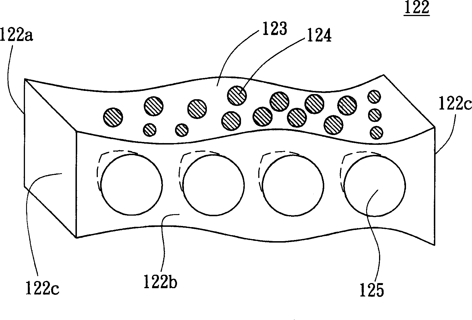
[0017] Please refer to figure 2 , which shows a cross-sectional view of the light emitting device according to Embodiment 1 of the present invention. exist figure 2 Among them, the light emitting device 115 at least includes a circuit board 111 , several light emitting diodes (LEDs) 112 , a first reflective material 126 , a diffusion structure 122 and several second reflective materials 127 . The LEDs 112 are disposed on the circuit board 111 and electrically connected to the circuit board 111 to provide light sources. For example, the LEDs 112 are composed of several red (R), green (G) and blue (B) LEDs.

[0018] The first reflective material 126 is disposed on the circuit board 112 , and the first reflective material 126 forms a plurality of through holes for the light-emitting surface of the LED 112 to protrude from the first reflective material 126 . After the first reflective material 126 is formed on the surface of the circuit board 111 by coating, the LED 112 can b...

Embodiment 2

[0024] Please refer to Figure 4 , shown in the figure is a cross-sectional view of a light emitting device according to Embodiment 2 of the present invention. The light emitting device 415 of this embodiment is different from the light emitting device 115 of Embodiment 1 in that the cross-sectional shape of the notch 425 of the light emitting device 415 is like an inverted end pyramid prism or pyramid shape, and other structures are similar to figure 2 The structure of the light emitting device 115 is the same, and will not be repeated here.

Embodiment 3

[0026] Please refer to Figure 5 , shown in the figure is a cross-sectional view of a light emitting device according to Embodiment 3 of the present invention. The difference between the light emitting device 515 of this embodiment and the light emitting device 115 of Embodiment 1 is that the cross-sectional shape of the notch 525 of the light emitting device 515 is like an inverted ellipse or ellipse at the end, and other structures are similar to figure 2 The structure of the light emitting device 115 is the same, and will not be repeated here.

[0027] The light emitting device disclosed in the above embodiments of the present invention has the following advantages:

[0028] 1. The design of its diffusion structure can increase the diffusion angle of LEDs with different luminous colors to achieve a more uniform light mixing effect.

[0029]2. Its diffusion structure can be in partial contact with the circuit board, which can avoid the bending phenomenon of the diffusion ...


PUM


Abstract

A light-emitting device includes circuit board, light-emitting diode, preliminary reflecting material and diffused structure. The light-emitting diode is fixed on the circuit board and connects with the circuit board to provide the lamp-house. The preliminary reflecting material is fixed on the circuit board and there are several via holes on the preliminary reflecting material for the light emitting area of the light-emitting diode to protrude the preliminary reflecting material. There are several notches at the bottom of the diffused structure and the diffused structure is fixed on the circuit board by means of covering the light-emitting diode with notches. The diffused structure has a transparent matrix and several diffused particles. The abovementioned diffused particles disperse in the transparent matrix. The light-house provided by the light-emitting diode becomes more uniform after the diffusion process of the diffused structure.

Description

technical field [0001] The present invention relates to a light emitting device, and in particular to a light emitting device capable of mixing light sources provided by red (R), green (G) and blue (B) light emitting diodes (LEDs) into more uniform white light light emitting device. Background technique [0002] Light-emitting diodes are electronic components that emit light when energized, and are light-emitting components made of semiconductor materials. According to the different colors of the light sources emitted, the light emitting diodes include red (R), green (G) and blue (B) light emitting diodes for emitting red light, green light and blue light respectively. In addition, because light-emitting diodes have the advantages of fast response speed, long luminous life, small size, low power consumption, low pollution and high reliability, light-emitting diodes can be easily mass-produced into array components, such as R, G and B light-emitting diodes The formed array ...

Claims


Application Information

Patent Timeline
IPC IPC(8): F21K9/23F21K9/235F21K9/65F21Y105/00F21Y113/13F21Y115/10G02F1/1335H01L25/075H01L25/13H01L33/00
Inventor 周信宏刘邦炫
Owner AU OPTRONICS CORP
Why Eureka
Try Eureka