Header for use in heat exchangers, heat exchanger and method for manufacturing the same

A technology for heat exchangers and heat exchange tubes, applied in the field of headers, can solve the problems of increasing the number of processing steps, cumbersome machining, and increasing manufacturing costs.

Inactive Publication Date: 2005-03-23
SHOWA DENKO KK
View PDF2 Cites 2 Cited by
  • Summary
  • Abstract
  • Description
  • Claims
  • Application Information

AI Technical Summary

Problems solved by technology

This requires cumbersome machining and increases the number of processing steps, which in turn increases manufacturing costs

Method used


Image

  • Header for use in heat exchangers, heat exchanger and method for manufacturing the same
  • Header for use in heat exchangers, heat exchanger and method for manufacturing the same
  • Header for use in heat exchangers, heat exchanger and method for manufacturing the same

Examples


no. 1 example

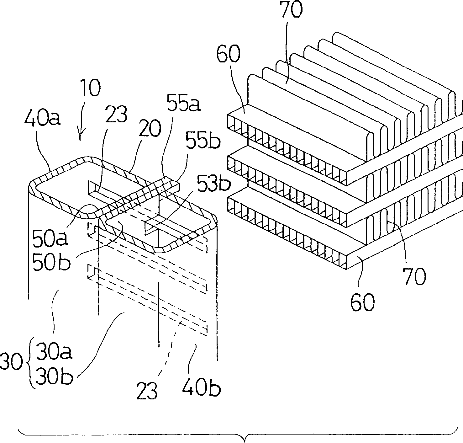
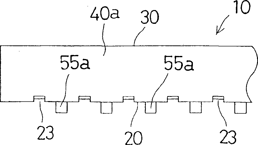
[0151] figure 1 6 to 6 show a header 10 applied to a heat exchanger according to a first embodiment of the present invention. As shown in these figures, the manifold 10 includes a strip-shaped base wall 20, an opposing wall 30 opposite to the base wall 20, a pair of side walls 40a and 40b, and a pair of reinforcing walls 50a and 50b disposed at a laterally central position between the base wall 20 and the opposite wall 30 and extending along the longitudinal direction of the header 10.

[0152] As shown in FIGS. 7 and 8, the header 10 is an integrally formed object obtained by bending a press-formed plate 11 having a predetermined shape formed by die-cutting press-forming. Specifically, the press-formed sheet 11 is a wide strip-shaped sheet. In the transverse central region of the plate 11 , the plate 11 has a base wall region 21 extending in the longitudinal direction of the plate 11 . This base wall region 21 will constitute the above-mentioned base wall 20 . On both si...

no. 2 example

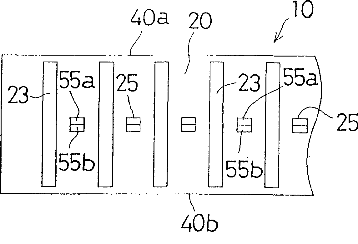
[0172] Figures 9 to 13 A header 10 for use in a heat exchanger according to a second embodiment of the invention is shown. As shown in these figures, in the same manner as the first embodiment, the press-formed plate 11 constituting the header 10 has a base wall region 21, side wall regions 41a and 41b, a first half opposing wall region 31a, a second Two halves of opposing wall regions 31b and first and second reinforcing wall regions 51a and 51b. On the base wall region 21, cannula openings 23 are provided at intervals.

[0173] Further, in the press-formed panel 11 , at the side edges of the first and second reinforcing wall regions 51 a and 51 b , insertion flanges 55 a and 55 b are alternately formed in the longitudinal direction of the panel 11 . Further, between the adjacent cannula openings 23 in the base wall region 21, first insertion flange engaging openings 25a and second insertion flange engaging openings corresponding to the insertion flanges 55a and 55b are al...


PUM


Abstract

A header for use in heat exchanger includes a base wall (20) with a plurality of tube insertion apertures (23), an opposite wall (30) opposed to the base wall (20), a pair of side walls (40a and 40b) disposed at both lateral sides of the base wall (20) and the opposite wall (30) and connecting the lateral sides and are inforcing walls (50a and 50b) disposed betwwen the base wall (20) and the opposite wall (30) along a longitudinal direction thereof and connecting the base wall (20) with the opposite wall (30). The side walls (40a and 40b) are integrally formed at both lateral sides of the base wall (20) be bending processing. A first half (30a) of the opposite wall (30) is integrally formed at a side of one of the side walls (40a) by bending processing, and a second half (30b) of the opposite wall (30) is integrally formed at a side of the other of the side walls (40b) by bending processing. Reinforcing walls (50a and 50b) are integrally formed at sides of the first half (30a) and the second half (30b) of the opposite wall (30) by bending processing. With this header for use in heat exchanger, high pressure resistance can be obtained, and the number of parts and the manufacturing cost can be decreased.

Description

[0001] This application claims the benefit of Japanese Patent Application No. 2001-95242, filed March 29, 2001, and US Provisional Application No. 60 / 302691, filed July 5, 2001, which are hereby incorporated by reference in their entirety. [0002] Cross References to Related Applications [0003] This application claims the filing date of Provisional Application No. 60 / 302,691, filed July 5, 2001, under 35 U.S.C. § 111(b). technical field [0004] The present invention relates to a header suitable for use in heat exchangers of condensers and evaporators in refrigeration systems such as automotive air conditioners, and to a method for manufacturing the header. Background technique [0005] As a condenser used in an air-conditioning system of an automobile, the so-called header having a pair of headers and a plurality of heat exchange tubes arranged in parallel with each other between the headers and communicating with the headers at their opposite ends is widely used. Tube ...

Claims


Application Information

Patent Timeline
Patent Type & Authority Applications(China)
IPC IPC(8): F28D1/053F28F9/02
CPCF28F2225/08F28D1/05383F28F9/0214F28F9/02
Inventor 渡边太川又保二星野良一小笠原升田村乔堀内博文寺田隆
Owner SHOWA DENKO KK
Why Eureka
Try Eureka