
Vehicle steering device

A technology for steering devices and vehicles, which is applied to steering columns, steering mechanisms, and steering controls mounted on vehicles. It can solve problems such as excessive body size, enlarged cross-sectional area, and complex structure of the steering device 200. It achieves reduced appearance, The effect of compact space and simple structure

Inactive Publication Date: 2005-04-06
HONDA MOTOR CO LTD
View PDF0 Cites 7 Cited by
  • Summary
  • Abstract
  • Description
  • Claims
  • Application Information

AI Technical Summary

Problems solved by technology

[0009] In the prior art mentioned above, since the multi-part linkage mechanism 204 and the universal coupling 211 are used to change the rotation angle of the steering shaft 206 relative to the rotation angle of the steering shaft 202, the structure of the steering device 200 is complicated. thus requiring a simplification of the structure
In addition, since the centerlines A1 and C1 of the steering shaft 202 and the steering shaft 206 are inconsistent, a large moment will act on the link mechanism 204 that transmits the rotational force. Therefore, in order to improve the rigidity of the link mechanism 204, For example, the cross-sectional area of ​​each component part will have to be increased, resulting in an excessively large shape

Method used


Image

  • Vehicle steering device
  • Vehicle steering device
  • Vehicle steering device

Examples


Embodiment Construction

[0044] Hereinafter, a preferred mode for carrying out the present invention will be described with reference to the drawings. In addition, the drawings are views in the direction indicated by the reference numerals.

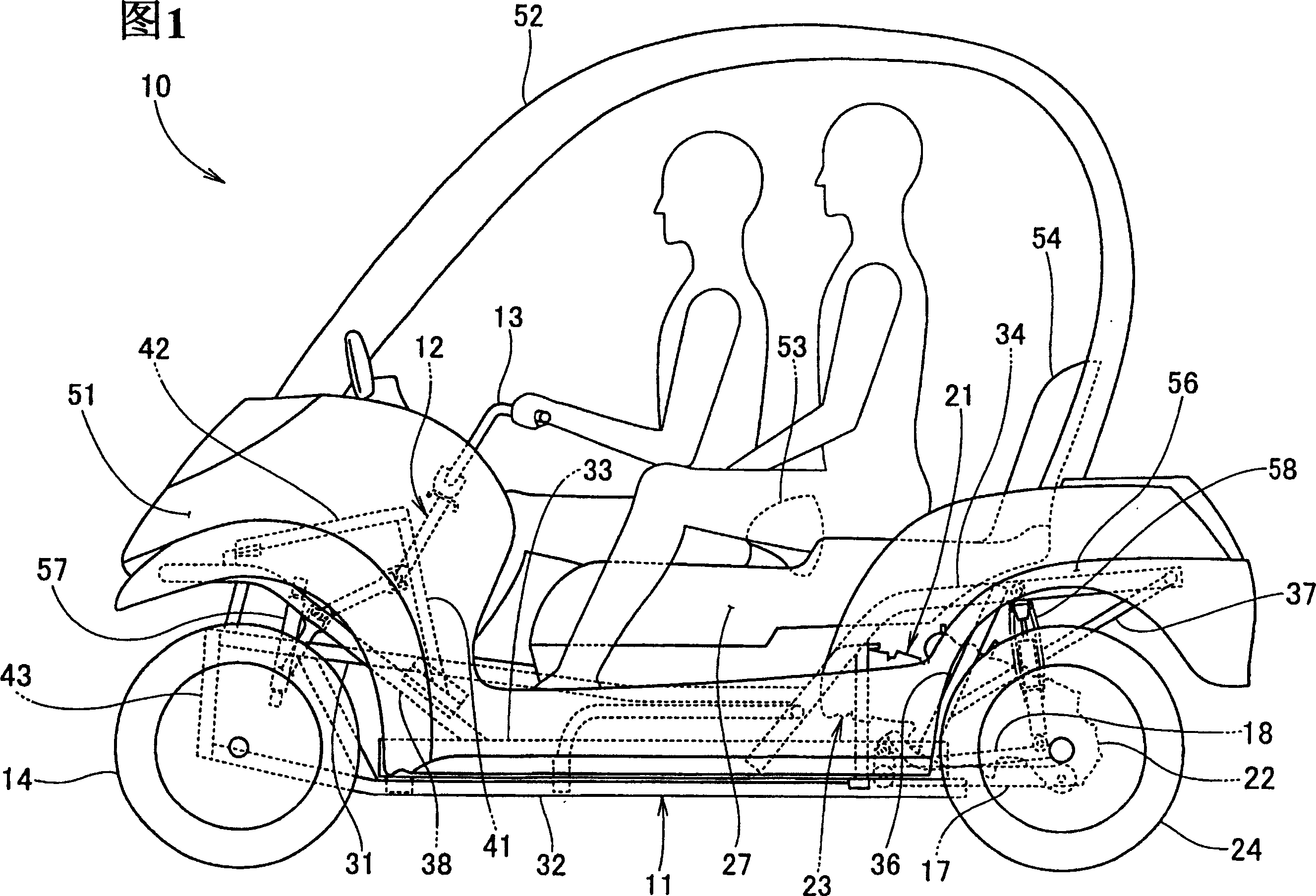
[0045] Fig. 1 is a side view of the vehicle of the present invention. The vehicle 10 is a two-person passenger four-wheeled vehicle. A separate steering shaft 12 is installed on the front of the body frame 11, and a handle 13 is installed on the upper part of the steering shaft 12. , To manipulate the front wheels 14, 15 as the left and right wheels (only the front number 14 is shown in the figure), the support arms 17 and 18 are installed at the rear of the body frame 11 by the engine 21 and integrally installed with the rear of the engine The power unit 23 constituted by the transmission 22 is equipped with rear wheels 24, 26 (only the front number 24 is shown in the figure) on the output shaft of the power unit 23, and a double seat 27 is installed on the upper pa...


PUM


Abstract

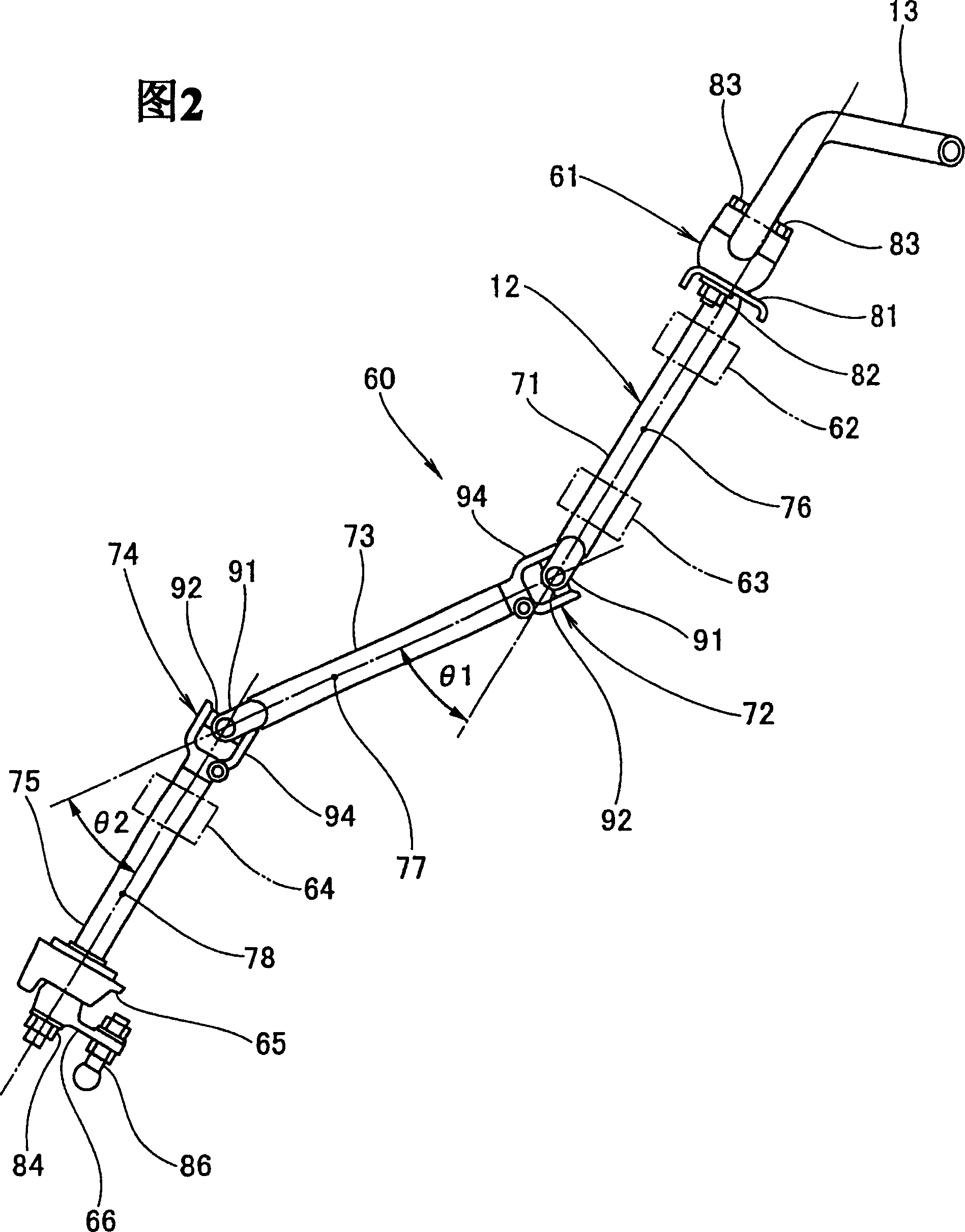
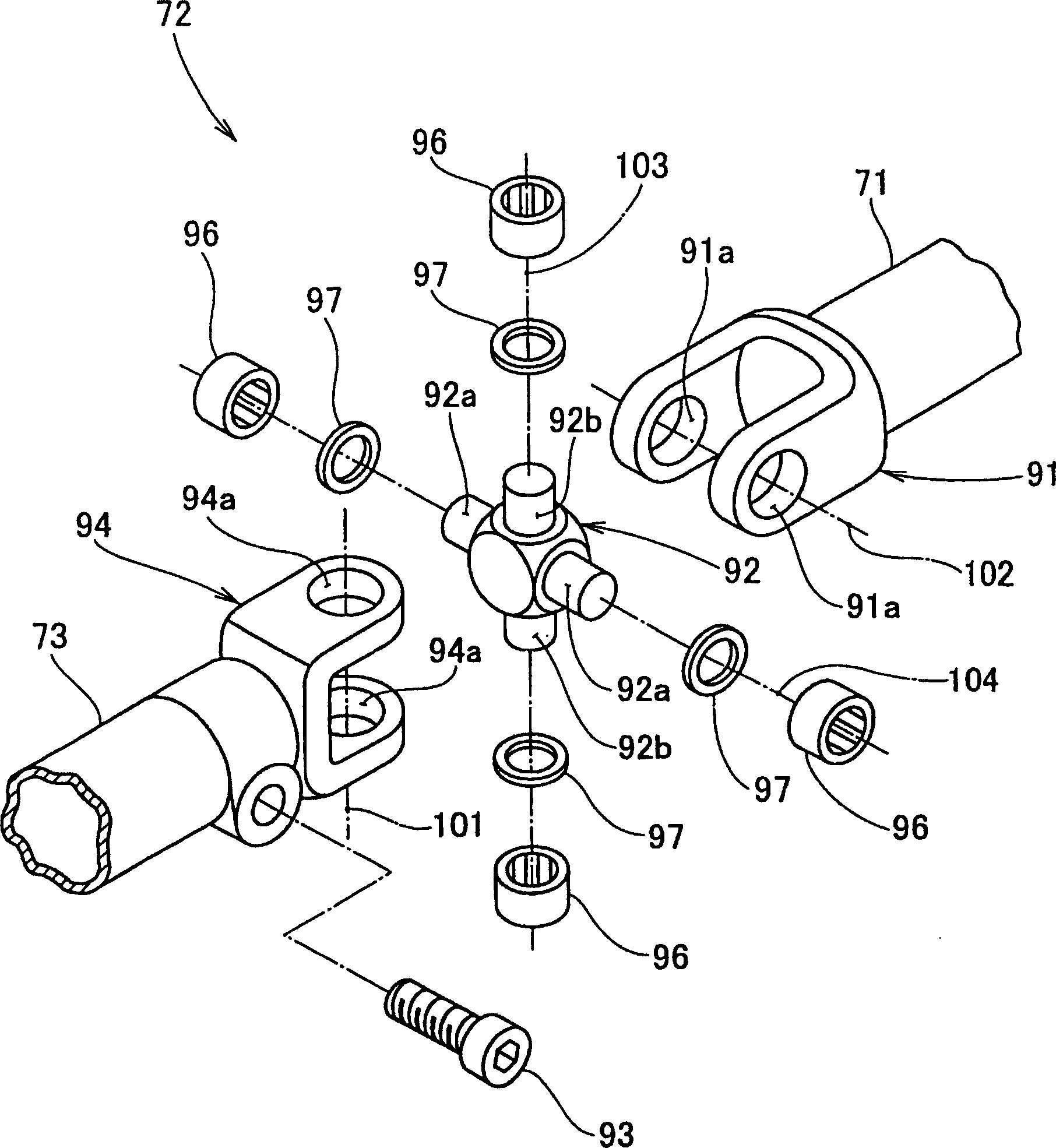
The vehicle is structured so that a steering shaft 12 is installed rotatably on a body frame, a tie rod and a knuckle arm are installed in the lower part of the steering shaft 12 through a steering arm 66, and wheels are mounted on the knuckle arm rotatably, wherein the steering shaft 12 is divided into a plurality of shaft sections (an upper shaft 71, a middle shaft 73, and a lower shaft 75), which are coupled together by hook type joints (a first hook joint 72 and a second hook joint 74).

Description

Technical field [0001] The invention relates to a vehicle steering device. Background technique [0002] In the related art, as a vehicle steering device, it is known that a steering shaft divided into two parts is connected by a link mechanism (for example, see Patent Document 1). [0003] [Patent Document 1] Patent Publication 2002-127981 Bulletin [0004] Through the following Figure 12 (a), (b) of the patent document 1 Figure 6 (a), (b) explain. And change the label. [0005] Figure 12 (a), (b) is a side view showing the main part of the conventional vehicle steering device, in Figure (a), the front wheel direction control device 200 as the steering device is free on the front fork tube 201 The steering shaft 202 is rotatably mounted, the connecting member 203 is mounted on the lower part of the steering shaft 202, the steering shaft 206 is mounted on the connecting member 203 through the link mechanism 204, and the steering shaft 206 is connected to the front wheel side . ...

Claims


Application Information

Patent Timeline
Patent Type & Authority Applications(China)
IPC IPC(8): B62K21/00B62D1/20
Inventor 关文三小关伸一折本俊宏
Owner HONDA MOTOR CO LTD
Learn More