Driver of combined part swing engine

A transmission and engine technology, applied in the direction of wheel transmission, transmission control, chain/belt transmission, etc., can solve the problems of large noise, large vibration of driven shaft 125, large space occupied by driven shaft 125, etc. , to achieve the effect of reducing noise and vibration

Inactive Publication Date: 2007-07-25
YAMAHA MOTOR CO LTD
View PDF4 Cites 0 Cited by
  • Summary
  • Abstract
  • Description
  • Claims
  • Application Information

AI Technical Summary

Problems solved by technology

[0007] However, the existing transmission shown in FIG. 4 has the following problems: Since the end of the driven shaft 125 on the side where the reduction gear 138 is provided is supported by the ball bearings 128, 129, the gear chamber S1 is enlarged, which not only causes The space occupied around the driven shaft 125 is large and the weight is heavy, and the shape and outer diameter of the hub of the rear wheel 142 are limited.
If the distance between the driving pulley and the driven pulley 130 is changed in order to make the diameter of the rear wheel 142 unrestricted, the service life of the V-belt 137 may be reduced, or the performance of the V-belt type automatic transmission itself may be reduced. reduce
[0008] In addition, there is also the problem that the distance between the supporting points supported by the ball bearings 128 and 129 of the driven shaft 125 is narrow, and a heavy object, that is, the driven pulley 130 and the centrifugal force, is supported on the protruding part of the driven shaft 125. type clutch 131, so the vibration of the driven shaft 125 is large and the noise is large

Method used


Image

  • Driver of combined part swing engine
  • Driver of combined part swing engine
  • Driver of combined part swing engine

Examples


Embodiment Construction

[0019] Hereinafter, embodiments of the present invention will be described with reference to the drawings.

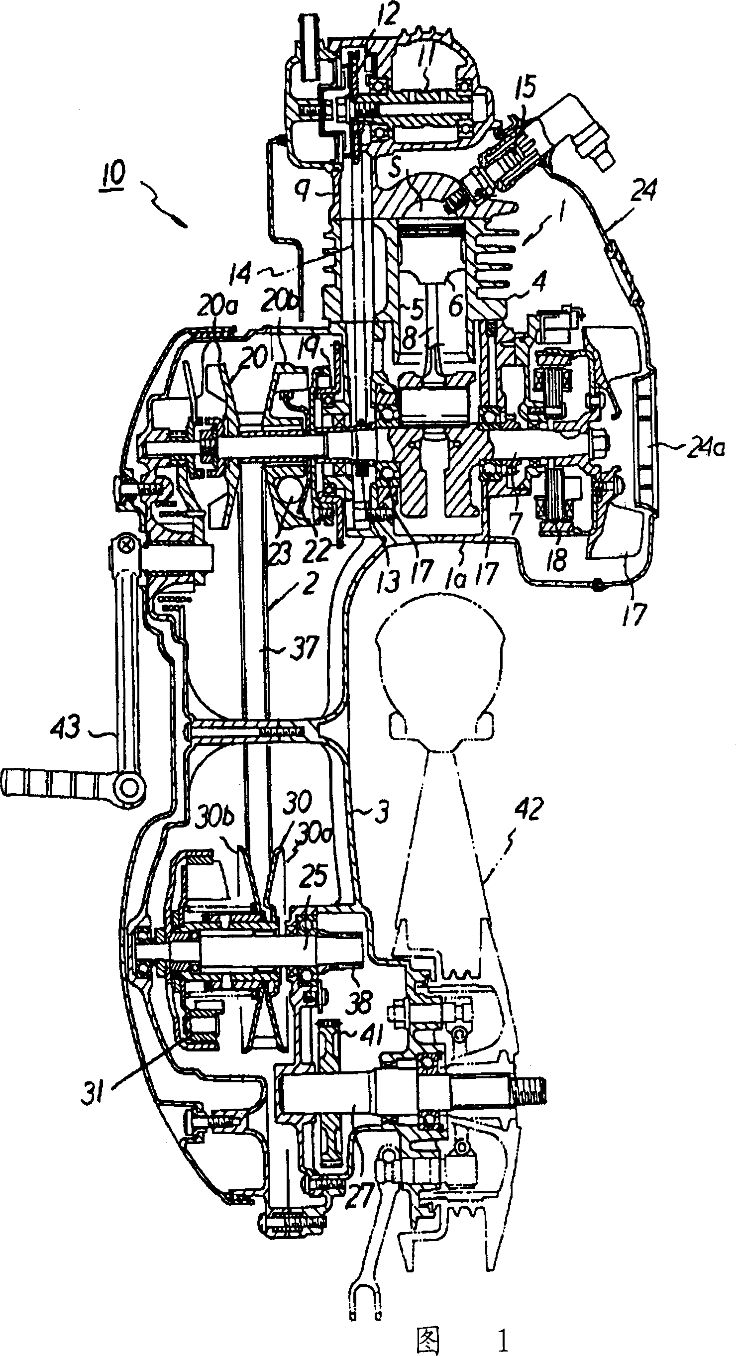
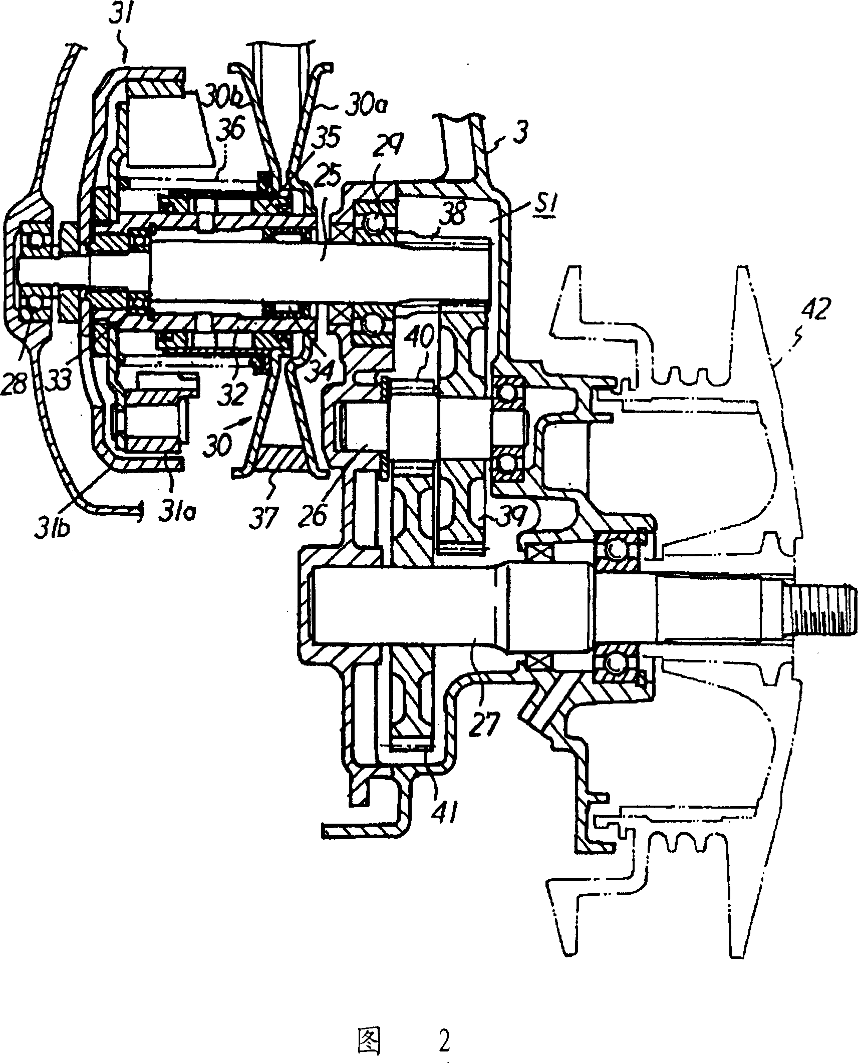
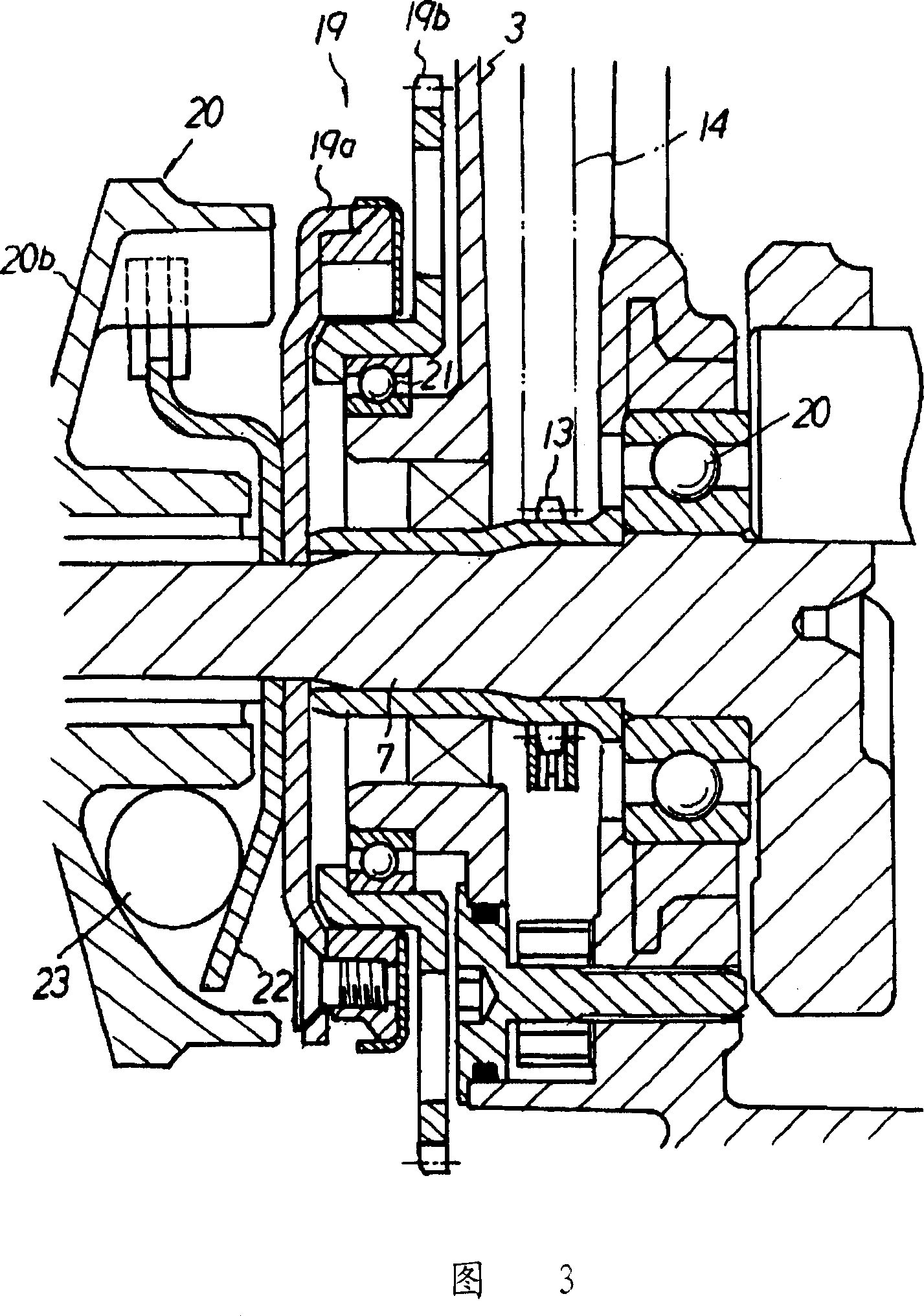
[0020] Fig. 1 is a transverse sectional view of an assembly swing engine, Fig. 2 is a partial transverse section view of an assembly swing engine showing the structure of the transmission device of the present invention, and Fig. 3 is a partial transverse section of a one-way clutch of an assembly swing engine picture.

[0021] Assembled swing type engine 10 shown in Fig. 1 is the engine that is contained on the small motorcycle type automatic two-wheel vehicle that is not shown in the figure, and it is the forced air-cooled 4 stroke engine (hereinafter referred to as engine) 1, and comprises V-shaped belt The automatic transmission device 2 and the transmission device of the deceleration device are compactly assembled as an assembly and constituted, wherein the automatic transmission device is arranged on the side extending from the left side of the crankcase 1a of the...


PUM


Abstract

This invention provides a transmission for a unit swinging type engine capable of securing a high degree of freedom in the hub shape of the rear wheel of a motorcycle while intending for a compact size around a driven shaft, a light weight, and noise reduction. In this transmission for a unit swinging type engine, a V belt type automatic transmission to transmit power to a driven shaft 25 extending in the width direction of a vehicle from a driving pulley supported by a crank shaft extending in the width direction of a body through a V belt 37 and a driven pulley 30, and a speed reducing gear to transmit power to an output shaft 27 from one end of the driven shaft 25 in the width direction of the vehicle through reduction gears 38-41 are disposed in a transmission case 3 extending toward the back of the body from one side of the crank case of the engine in the width direction of the vehicle. The driven shaft 25 is disposed parallel to the output shaft 27 by separating them frontward and backward, the driven shaft 25 is doubly supported by a pair of right and left bearings 28, 29, and the driven pulley 30 of the V belt type automatic transmission is supported between the right and left bearings 28, 29 of the driven shaft 25.

Description

technical field [0001] The present invention relates to a transmission for a combined swing engine. Background technique [0002] The assembly swing type engine that is contained on the automatic two-wheel vehicle of small motorbike type is that engine and the transmission device that comprises V-belt type automatic speed changer and deceleration device are assembled into one and constituted as assembly. [0003] The above-mentioned V-belt type automatic transmission is constructed in such a way that the movable pulley is freely slidable along the crankshaft between the fixed pulley fixed on the crankshaft (drive shaft) of the engine and the cam disc, and the centrifugal balance weight is stored in the Between the movable pulley and the above-mentioned cam disc, a V-shaped belt is wound between the driving pulley and the driven pulley, wherein the driving pulley is composed of the above-mentioned movable pulley and the above-mentioned fixed pulley, and the driven pulley is a...

Claims


Application Information

Patent Timeline
Patent Type & Authority Patents(China)
IPC IPC(8): F02B61/06B62M9/08B62M7/12B62M11/02F02B61/02F02B75/16F16H63/06
CPCF02B75/16B62M7/12B62K2202/00F02B61/02
Inventor 奈良一弘猪森俊典
Owner YAMAHA MOTOR CO LTD
Why Eureka
Try Eureka