
Sensing unit for magnetic resistance spinning valves temperature control switch

A temperature-controlled switch, spin valve technology, applied in temperature control, non-electric variable control, instruments, etc., can solve problems such as inability to CMOS circuits, unchangeable, and inability to freely set temperature thresholds

Active Publication Date: 2005-04-06
INST OF PHYSICS - CHINESE ACAD OF SCI
View PDF1 Cites 7 Cited by
  • Summary
  • Abstract
  • Description
  • Claims
  • Application Information

AI Technical Summary

Problems solved by technology

At present, the temperature sensors on the market mainly include diode temperature detectors, which are mainly used to monitor and protect the CPU in computers (typically MaximIntegrated Products MAX6511 / MAX6512, MAX1617, etc.), generally used in notebook computers, desktop PCs, servers or workstations , In addition, there are various resistance temperature sensors widely used in industry, such as Pt resistance wire or thin film resistance temperature sensors, diode temperature detectors are compatible with CMOS circuits, but the temperature threshold of each device is set by the manufacturer and cannot be changed
The Pt resistance wire or thin film resistance temperature sensor cannot freely set the temperature threshold, and is not compatible with CMOS circuits. To set the temperature threshold, additional electronic components are required, and once set, it cannot be changed.

Method used


Image

  • Sensing unit for magnetic resistance spinning valves temperature control switch
  • Sensing unit for magnetic resistance spinning valves temperature control switch

Examples


Embodiment Construction

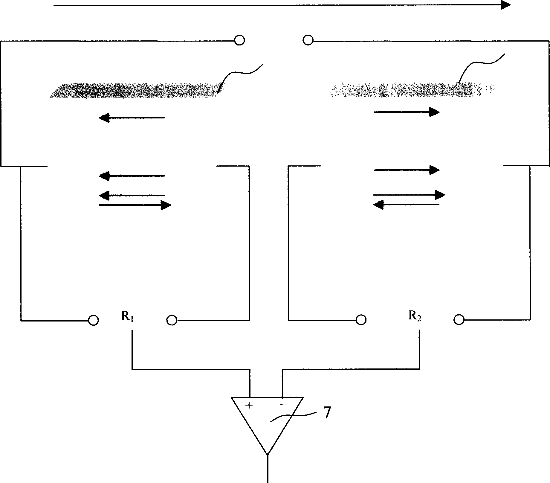
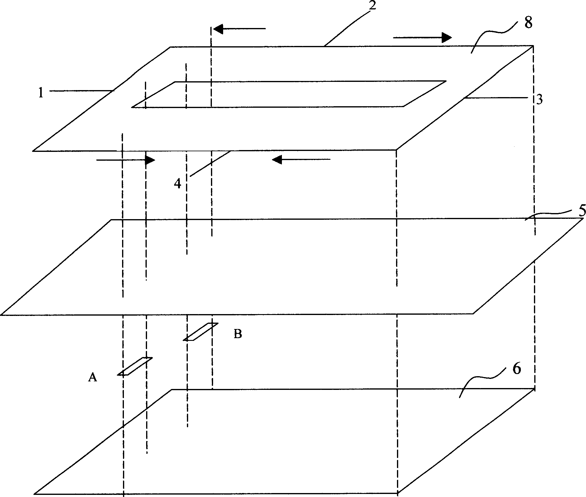
[0008] Such as figure 1 , 2 As shown, the present invention includes a chip base 6, a comparator 7, an insulating layer 3 and a fixed conductive layer 8, and the fixed electrical conductor includes and two power terminal pins 1, 3 and 2, 4; Formed with two spin valve elements A, B, such as figure 2 As shown by the dotted line in the middle, the fixed electric conductor layer 8 must cover the long sides of the two spin valve elements A and B, and an insulating layer 3 is arranged between the two spin valve elements and the fixed electric conductor, applied on the spin valve The magnetic field on the elements A and B is controlled by the current passing through the fixed electric conductor layer 8; the resistances of the spin valve elements A and B are compared by the comparator 7, and when the resistances of the spin valve elements A and B are not equal output signal. The spin valve elements A and B are formed on the substrate by photolithography or mask method, so that the...


PUM


Abstract

This invention discloses a magnetic resistance spin valve switch sensor, which comprises one base, one comparator, one isolation layer and one fixed conductor. The base is formed with two spin valve elements between which and conductor there located the isolation layer. The magnetic field of the spin valve element resistance changes are controlled through the current of fixed conductor. It compares the two spin valve elements resistance and outputs signal when the two resistance values are unequal.

Description

technical field [0001] The invention relates to a temperature control switch sensor made by using a giant magnetoresistance (GMR) spin valve. Background technique [0002] The coercive force of many ferromagnetic materials is related to temperature, and generally decreases gradually with the increase of temperature. There are many related documents, such as Appl.Phys.Lett.Vol 77, 2731, 2000 mentioned in giant magnetic Co commonly used in resistance optional valve material. Such a method is described in a patent (Application No. 95105085.0) published by IBM Corporation of the United States, that is, a conductive fixed layer is formed on the substrate to insulate from the respective spin valve elements. At present, the temperature sensors on the market mainly include diode temperature detectors, which are mainly used to monitor and protect the CPU in computers (typically MaximIntegrated Products MAX6511 / MAX6512, MAX1617, etc.), generally used in notebook computers, desktop PC...

Claims


Application Information

Patent Timeline
IPC IPC(8): G01K7/38G05D23/26
Inventor 王磊丰家峰张谢群韩秀峰
Owner INST OF PHYSICS - CHINESE ACAD OF SCI
Learn More