Rotary powder compression molding machine

A compression molding and rotary technology, applied in the direction of presses, material forming presses, electrostatic spraying devices, etc., can solve problems such as contamination, uneven adhesion of powder lubricants, and half the manufacturing speed of tablets, so as to prevent scattering Effect

Inactive Publication Date: 2005-04-06
KIKUSUI SEISAKUSHO LTD
View PDF0 Cites 6 Cited by
  • Summary
  • Abstract
  • Description
  • Claims
  • Application Information

AI Technical Summary

Problems solved by technology

[0005] However, in the former method, when spraying, the powder lubricant is scattered around and mixed into the drug prescription ingredients, or conversely, the drug prescription ingredients are mixed into the powder lubricant when sprayed, causing a so-called contamination problem, and the powder lubricant The agent sometimes does not adhere evenly to the pestle, etc.
In addition, in order to prevent scattering, a method of enclosing the periphery of the pestle rod at the position where the powder lubricant is sprayed was considered, but it was difficult to provide an opening for the powder lubricant to pass through the surrounding member for the upper pestle rod. Suppress the fly
[0006] In addition, in the latter method, a compression mechanism for compressing the powder lubricant is required, resulting in an increase in the size of the device, and the tablet manufacturing speed is also reduced by half compared to usual
Although various other methods have been considered, the same problem arises when actually manufacturing tablets

Method used


Image

  • Rotary powder compression molding machine
  • Rotary powder compression molding machine
  • Rotary powder compression molding machine

Examples


Embodiment Construction

[0037] Next, an embodiment of the present invention will be described with reference to the drawings.

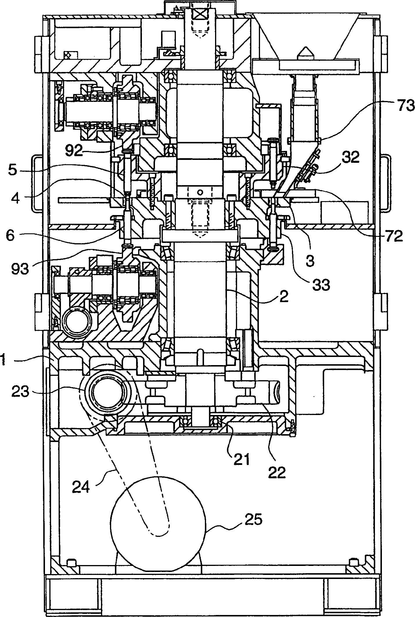
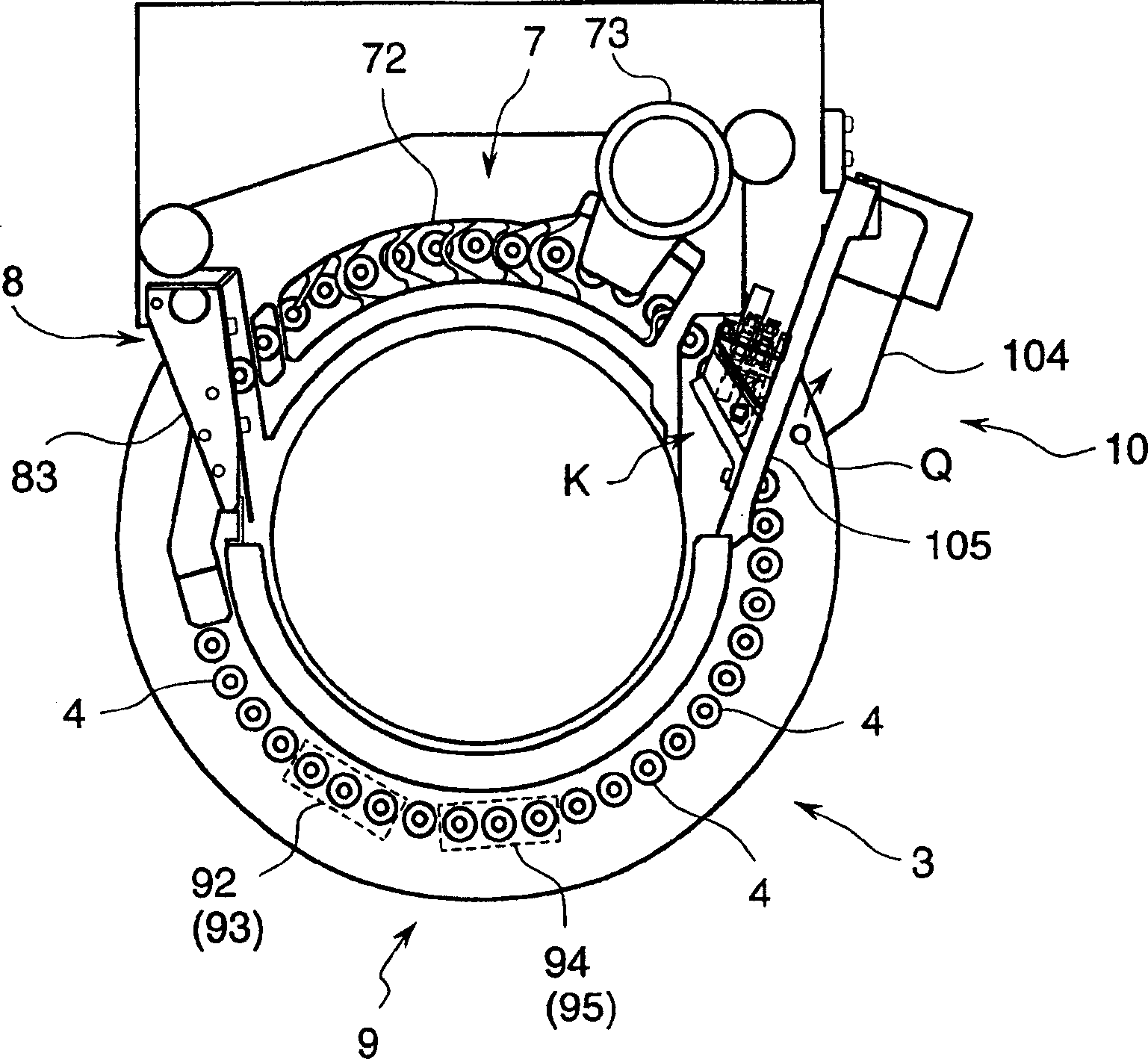
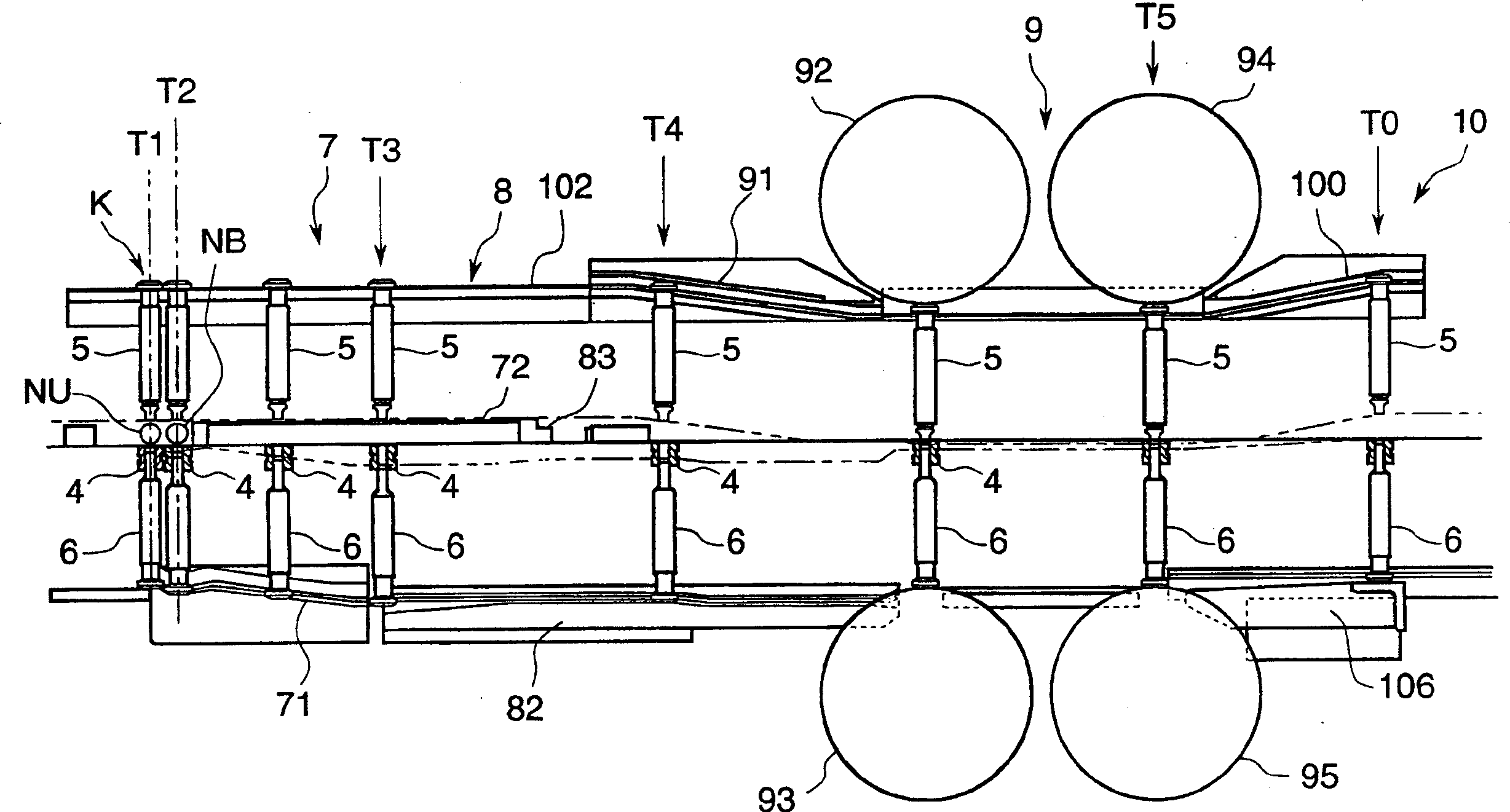
[0038] figure 1 In , the overall structure of the rotary powder compression molding machine of the present invention is shown. This rotary powder compression molding machine is equipped with a powder lubricant injection device LS ( Figure 9 ). In the frame 1, a rotating disk 3 that can rotate horizontally is arranged through a vertical shaft 2. On the rotating disk 3, several mortars 4 are arranged at predetermined intervals. The last pestle rod 5 and the following pestle rod 6.

[0039]Specifically, a vertical shaft 2 supported by a bearing 21 is disposed at approximately the center of the frame 1, and a worm wheel 22 is fixed near the lower end of the vertical shaft 2. As shown in FIG. The rotational driving force of the motor 25 is transmitted to the worm wheel 22 through the worm 23 and the belt 24 . Near the head of the vertical shaft 2, a rotating disk 3 divided ...


PUM


Abstract

In a rotary compressive molding machine for powder material wherein powder material filled in a die hole of a die mounted on a rotary table is compressed and molded between a lower end face of the upper punch and an upper end face of the lower punch, a powder lubricant spraying means that sprays powder lubricant comprises a spray nozzle that has a concave face facing to the lower end face of the upper punch or the upper end face of the lower punch at a position where the powder lubricant is sprayed and that sprays the powder lubricant generally toward a direction of the lower end face of the upper punch or the upper end face of the lower punch guided by the concave face, an air current supply mechanism that prevents the powder lubricant sprayed from the spray nozzle from scattering upward by spraying air near the lower end face of the upper punch, and an electrostatic charge device that electrizes the powder lubricant when the powder lubricant is sprayed from the spray nozzle and that electrizes at least the upper punch, the lower punch and the die with an antipolarity against the electrized powder lubricant.

Description

technical field [0001] The present invention relates to a rotary powder compression molding machine for compression molding powder into tablets and the like. Background technique [0002] In the past, when such a rotary powder compression molding machine was used to manufacture tablets, if the raw material powder of the tablet was composed of only the ingredients of the drug prescription, the raw material powder of the tablet or the tablet would stick to the pestle and the mortar, causing problems such as so-called sticking. . In order to prevent this sticking, a powder lubricant such as magnesium stearate is mixed into the drug prescription ingredients, and the method of manufacturing the tablet from the raw material powder constituting the tablet is easy in the manufacture of the tablet, so this method has generally been used in the past. [0003] In recent years, medical care for the elderly has been emphasized, and there has been an increasing demand for tablets that di...

Claims


Application Information

Patent Timeline
Patent Type & Authority Applications(China)
IPC IPC(8): B05B1/26B05B5/03B05B7/14B05B15/12B30B15/00
CPCB05B15/1285B05B5/0533B05B7/1454B05B1/267B05B5/032B30B15/0011B05B14/45
Inventor 岛田启司小根田好次
Owner KIKUSUI SEISAKUSHO LTD
Why Eureka
Try Eureka